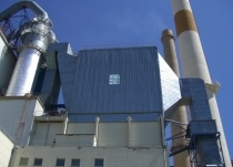
Process filter trends in the cement industry

Summary: Process filtration in the cement industry has shown a dynamic development in recent years. It is to be expected that dust emission limits will be made even more stringent in the near future and that particularly the filter media of the latest generation will consequently increase their market share from about 10 % to over 40 %. Simultaneously, the demand for pure electrostatic precipitators will continue to fall and, instead, bag filters and hybrid filters will expand their market shares. This will also affect the up-and-coming cement markets in China, India and Africa. This article provides an overall view of the development of emissions in the cement industry and of current trends in filtration technology.

1 Introduction

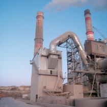
In 1950 the dust emission level of cement factories in the ­leading western countries was still around 3.5 kg/t of cement. In other words, cement production lines with an output of 3000 tpd had an annual emission rate of 3500 t of dust. For local residents, hanging white washing out to dry was not without risk. Nowadays, the maximum annual emission rate of modern 5000 tpd lines is 250 t and it is no longer possible for local residents to see cement dust on their white washing with the naked eye. Emission limit values of less than 20 mg/Nm3 can be easily observed with available technology. The best plants meanwhile achieve emission rates of less than 5 mg/Nm3. In Germany, for example, a country that does not exactly have a reputation for lax environmental laws, practically all cement factories have dust emissions below the level relevant for ­environmental data registration. Their output levels are below the threshold value of 50 t/a of particulate matter (PM10 = Particulate ­Matter <  10 µm).


Despite this achievement, the environmental authorities still view the situation with some suspicion because the particulate matter emitted nowadays is partially respirable and has a content of up to 1 % heavy metal and other non-volatiles. Environmental authorities are guided by the concept of best available technology [1], relatively independent of the cost involvement. For instance, the US environmental authority EPA (Environmental Protection Agency) has moved to further reduce the PM limit value of the cement industry from the present 0.15  kg/t of clinker to 0.04 kg/t as from 2013. The Portland Cement ­Association (PCA) expressed the reservation that such low limit values are not yet attained by US cement factories. It also argues that a further toughening of environmental regulations will ­result in an exodus of cement producers to countries with lower requirements. This article has the intention of outlining process filter trends and discussing the extent to which limit values below 0.05 kg/t of clinker can actually be attained.


2 Situation of the cement industry

It is obvious that the cement industry and especially the leading cement producers are making considerable efforts to further reduce dust emissions in coming years. The sustainability reports of cement producing companies and national cement associations provide a large amount of relevant information on this subject. The dust emission figures of individual companies largely depends on the proportion of their output capacity in “emerging markets”, on what emission limit values exist in the countries involved and on the state of technology of the old plants. When purchasing such plants, the declared aim of global producers was to bring them up to the state of the art.


In China for instance, Lafarge - who operates approx. 50 cement kilns in a joint venture – succeeded in reducing dust emissions by 57  % between 2005 and 2007. In addition, 16 kilns were totally shut down. Also in countries like Russia, the Ukraine and Greece, emissions were drastically cut by installing modern filters. 60  % of Lafarge‘s kiln plants emit dust quantities of lower than 50 mg/Nm3. In 2010, Lafarge aims to achieve this figure in all of its cement factories. The specified company standard is, however, 30 mg/Nm3. On average, the dust emission of Lafarge factories dropped from 241 g/t of clinker in 2005 to 208 g/t of clinker in 2007. This corresponds to a reduction of 13.7  %. The company‘s voluntary commitment programme provides for a dust emission reduction of 30  % over the period from 2005 to 2012.


In the case of Holcim, the dust emission in 2005 was 150 g/t of cement material, while in 2007 it was 110 g/t of cement ma­terial. As is customary on the cement sector, dust quantities are referred to the emissions at the kiln stack. Figure 1 shows how Holcim’s specific dust quantities have changed in recent years. The total emissions of all the company’s factories have fallen from 18.4 kilotons/year to 17.7 kt/year, while cement output has risen to 155.9 Mta and the clinker factor was reduced from 75.2  % in 2005 to 72.6  % in 2007. Holcim thus achieved a reduction from 199 g to 152 g per tonne of clinker. Among the global players of the cement industry, Holcim thus has one of the lowest dust emission figures. Cemex reduced its dust emissions from 219 g/t of clinker in 2006 to 162 g/t of clinker in 2008. Taking account of a decrease in the company’s production output, the absolute emission figure dropped from 12.85 to 9.1 kt/year. Cemex aims to reduce the specific emission rate to 155 g/t by 2015.


HeidelbergCement’s dust emission figure remained practically unchanged in the years 2005 and 2006 with 275 and 278 g/t of clinker. Its absolute dust emission was 16.6 kt/year. Italcementi was only able to reduce its specific dust emission rate from 199 to 187 g/t of clinker from 2006 to 2007. In the so-called ­“mature markets” Italcementi’s specific dust load is only 26  g/t of clinker, but in the “emerging markets” it is more than ten times higher, at 304 g/t of clinker (Fig. 2). It is particularly interesting that in 2005 Italcementi‘s dust emission figure for the “emerging markets” was already 126 g/t of clinker, but then deteriorated considerably due to subsequent acquisitions in 2006. While Italcementi‘s dust emission in the “mature ­markets” was only 0.63 kt/year in 2007, the figure for the “emerging markets” was 7.8 kt/year.


In the cement industry, the subject of dust emission is increasingly being coupled with the question of the extent to which dangerous wastes are burnt as secondary materials. On the one hand, cement factories have the advantage vis à vis conventional incineration plants that their combustion temperatures are extremely high and that the retention times in the kiln system are relatively long. However, on the other hand it is possible for concentrations of non-volatile substances, particularly heavy metals such as arsenic, lead, cadmium, thallium etc., to occur in the emitted particulate matter. For cement projects that are partially financed, for example by the IFC (International Finance Corporation), this is taken into consideration in the stipulated limit values. Whereas the normally permitted particulate matter emission is 30  g/Nm3, the limit value is lowered to 10 g/Nm3 if more than 40  % of the employed fuel is made up of dangerous waste material.


3 Process filters in cement factories

It is inherent in the cement manufacturing process that dusts are produced during the quarrying of material, and the grinding, burning, cooling, conveying, storage, packing and dispatch processes. In order to prevent the occurrence of uncontrolled dust emissions, filter systems are installed in the individual machines of the various process stages. However, this has the disadvantage that enormous quantities of exhaust gas have to be dedusted during the cement manufacturing process. In the process equipment there are three main dedusting tasks: raw mill/kiln system, clinker cooler/kiln bypass and cement grinding plant. The filters employed in all of these cases have to satisfy the following main requirements:


a) ensure compliance with the emission limit values

b) minimize the created pressure drop

c) operate with a low kWh and compressed air consumption

d) have a long service life and high availability

e) involve the lowest possible capital cost.

To fulfil these requirements, the filters are equipped with internal flow guidance systems that ensure a uniform gas distribution over the filter elements and minimize the gas inlet velocities. That this is not an easy undertaking becomes clear when one considers that the dedusting systems for kiln and raw mill have to deal with an exhaust gas volume of over 2 million Am3/h. The exhaust gas volume fed to the dedusting systems for the cement mill, and for the cooler and bypass is somewhat lower, at 1 and 0.5 million Am3/h respectively. But these systems, too, are equipped with compact filters with net filter area loadings of 1–1.5 m3/m2 min for gas dust loads of 1000 g/Am3. ­Another critical aspect for the filters is the very high exhaust gas temperatures in some sections of the plant. For this reason, especially the kiln and cooler exhaust air filters are provided with gas conditioning systems or air/air-heat exchangers.


In the cement industry, electrostatic precipitators and fabric filters (bag filters), or combinations of the two processes, have established themselves as the most important types of process filter. There is a clear trend towards bag filters, which enable compliance with lower emission limit values than electrostatic precipitators and are practically independent of operating conditions and plant starting and stopping phases. In the case of electrostatic precipitators, the separation efficiency, i.  e. the dust collection rate, depends on the raw gas temperature and the electrical resistance of the dust particles, which can fluctuate depending on, for instance, the temperature or humidity. A further problem is presented by the high process-related CO concentration, which can even cause emergency shutdown of the electrostatic precipitator [1]. Gravel bed filters are sometimes still used as preliminary filters for clinker cooler dedusting systems. If used as the sole filter, the collection efficiency of a gravel bed filter does not correspond to the state of ­technology.


3.1 Bag filters (fabric filters)

For use as process filters, the cement industry prefers jet-pulse filters to filters cleaned by rapping or shaking. The dust particles are collected on the surface of the filter medium or on the filter cake formed on the surface. A jet-pulse filter (Fig. 3) is divided into compartments for the raw gas and for the clean gas [3]. The raw gas flows into the inlet housing with a velocity of more than 10 m/s and special internal systems then uniformly distribute it in longitudinal and transversal directions at velocit­ies of 1–1.2 m/s to the filter bags. The gas flows through the bags, which have standard lengths of 6–8 m, from the outside to the inside [4]. Inside the filter bags the gas flow rate is only about 0.02 m/s. After flowing through the filter bags, the clean gas leaves the filter at the head. The dust particles are deposited in the collecting cone, from which the material is usually evacuated by screw conveyors. The filter media are cleaned by pulses controlled either by time interval or by differential pressure. Changing of the filter bags is carried out at the head of the filter unit.


The pressure drops of the filter results from a portion Δp1 for the filter cake, Δp2 for the filter medium and Δp3 for the filter housing, which also includes all other pressure drops. The residual pressure drop Δp0 after the pulse cleaning is employed as the pressure drop for the filter medium. Improvements in the pulse cleaning process have successfully reduced the energy consumption of bag filter units in recent years. Shutoff devices on the raw gas and/or on the clean gas side switch the individual filter modules into an offline or semi-offline condition for cleaning. This prevents immediate deposition of the detached dust on neighbouring filter bags and additionally enables the cleaning system to operate with a compressed air pulse of lower intensity than that of conventional jet-pulse filters.


Low-pressure systems with pressure differences of 1 to 3 MPa and relatively long cleaning cycle times have proven effective for the pulse cleaning process. These provide the particular benefits of longer bag service lives and lower energy requirement. In conjunction with special propulsion jet nozzles with sec­-ondary air injection, these measures reduce the compressed air consumption significantly and also lower the energy requirement (LPVP process = low pressure - low volume) [4]. However, the energy required for the production of compressed air is relatively low in relation to the total energy requirement of the filter, so that other processes focus on reducing the pressure drop of the filter medium and filter cake. For instance, the Three E process (Fig. 4), which stands for “Enhanced Energy Efficiency”, makes use of new filter media and also employs cycle times of <  150 s [5]. This results in energy savings of up to 40  %.


3.1.1 Kiln and raw mill dedusting

Kiln filters are usually designed to handle interconnected operation of kiln and raw mill. In this mode of operation, the kiln and preheater exhaust gases with temperatures of 250 to 350 °C are either partially or completely utilized for combined grinding and drying in the raw mill. Vertical mills are mainly used for this purpose [6]. In many grinding circuits a mill bypass with exhaust gas conditioning is installed, so that the kiln exhaust gases can be completely passed through the bypass duct if the mill is not in operation (Fig. 5). In this configuration, the mill must be equipped with a separate mill system fan that can overcome the differential pressure of the mill and the pressure drop of the collection cyclone downstream of the mill. Whether or not interconnected operation is in use, the exhaust gas enters the filter at a temperature of around 120 to 230 °C. If the kiln exhaust gas is not used for combined grinding and drying, the operating mode is called mill bypass operation.


Bag filters are insensitive to load peaks caused by kiln operation, e.g. a change of fuel or similar. Figure 6 shows a process filter for kiln/mill system dedusting at Dyckerhoff. The raw gas stream is max. 240 000 Am3/h, the exhaust gas temperature <  230 °C and the filter area is 4010  m2 or 3700  m2 net during semi-offline operation. The filter bags are cleaned periodically and dependent on differential pressure of the filter with compressed air with a pressure of approx. 2.5 bar. The pressure drop is 10-11 mbar and the compressed air consumption <  45  Nm3/h. The filter has no problem meeting dust limit values <  10  mg/Nm3 [7]. A kiln filter (Fig. 7) is installed at the Cesla factory of HeidelbergCement in Russia. This filter works in mill bypass operation and is designed for a gas flow volume of 210 000  Am3/h. The filter inlet temperatures are between 150 and 180 °C. The raw gas dust concentration is 78  g/Nm3. This filter operates with a pressure drop of 15 mbar and a compressed air consumption of 30 Nm3/h. Dust limit values < 10  mg/Nm3 are easily achieved [4]. 


3.1.2 Clinker cooler and kiln bypass dedusting

Coolers with no exhaust air failed to establish themselves and have disappeared from the market. The vast majority of clinker coolers in use today are of the reciprocating grate type and have a tertiary air duct connection to the cyclone preheater of the kiln. The specific cooling air volumes are approx. 1.7–1.9  Nm3/kg of clinker, of which about 2/3 are recuperated and 1/3 has to be dedusted as cooler exhaust air. Depending on the system involved, the exhaust air volume can reach 0.5 million Am3/h. The exhaust air temperatures are 250 to 350 °C, but can reach peaks of around 500 °C during so-called “upset conditions”. To cope with these conditions, cyclones and air/air heat exchangers are installed upstream of the filters (Figs. 8 and 9). The cyclones reduce the dust concentrations of up to 75 g/Am3 by around 70  % for the heat exchanger. The heat exchanger cools down the exhaust air to permanent temperatures of 135 to 200 °C that are acceptable for the polyester or Nomex filter bags. To reduce any temperature peaks, a controllable fresh air damper is installed in the heat exchanger.


Due to the increasing use of secondary fuels, chlorine, sulphur and alkalis often enter the kiln process. When kiln dust is ­recirculated into the process, an internal cycle of these substances is created in the kiln system. A bypass of 5 –10  % enables a portion of the dust-laden kiln exhaust gas to be discharged from the process. In the recent past, bypass systems have frequently been equipped with a common filter for kiln bypass gas and cooler exhaust air [8]. The Castle Cement works has a bypass filter working as a separate process filter (Fig. 10) for a kiln gas bypass of 7 %. Here, the raw gas flow volume is approx. 107 000  Am3/h, the gas temperature is 220 °C (max. 260 °C), the filter area is 2375 m2 and the specific filter loading is thus 0.75  m3/m2 min. The filter enables the observance of dust limit values <  5  mg/Nm3.


3.1.3 Cement mill dedusting

In the dedusting system of the cement grinding plant, the downstream filter has the function of collecting the finished product that is transported in the air stream. The encountered air volumes and dust loads depend on the grinding process employed. The air volumes coming from vertical mills are about twice as high as those from, e.  g., ball mills or roller presses, which are equipped with separate separators. While the dust load of air from vertical mills is in the range of 200 – 500  g/m3 and contains particle sizes over the entire spectrum of finished material, the direct collection of finished product coming from separators is typified by extremely high dust loads of up to 1000  g/m3 and by a portion of ultrafine particle sizes, if – for instance – closed circuit cyclone separators are used for the pre-collection. Although the range of energy requirement for dedusting vertical mills is higher in comparison with ball mills and combinations of ball mills/roller presses, the required system configuration is relatively simple.


In the case of ball mill/separator material circuits, a separate dust collection filter is generally used for the ball mill and a process filter is needed for the separator. If there are several separators, they are generally decoupled by the use of separate filters. For the process filter, uniform intake flow over the entire filter area is important because of the high dust loads and air flow volumes involved. Figure 11 shows a mill filter for a vertical mill at Atlantica Cement in Spain. Here, the mill exhaust air stream is 400 000 Am3/h, the specific filter loading is 0.94  m3/m3 min and the dust load is 350  g/m3. The filter has a pressure drop of 9  mbar, a compressed air consumption of 86  Nm3/h and achieves dust values below the limit of 20  mg/Nm3.


3.2 Electrostatic precipitators

Up to around 1980, practically all kiln and cooler exhaust dedusting systems employed electrostatic precipitators. Nowadays, there is a strong downward trend in most countries because of more stringent emission limit values. Strictly speaking, these electrostatic dust collectors cannot be referred to as filters. “Electrostatic dust collectors” essentially consist of parallel gas channels between metallic collecting electrodes. Between the collecting electrodes there are discharge electrodes which are supplied with high voltage to create a corona discharge from their surface (Fig. 12). Due to the corona effect, dust particles are electrically charged by the adhesion of gas ions and are subsequently deposited on the collecting electrodes. With this ­system, dust emission rates <  50  mg/Am3 can be achieved and in certain cases it is even possible to observe limits of ­20 –30  mg/Am3.


However, in contrast to bag filters, it is not possible to adhere to absolute dust emission limit values with electrostatic precipitators. There may be problems, for example, during cement plant starting-up and shutting-down phases and “upset conditions”. The specific electrical resistance of the dust particles and the gas temperatures, moisture contents and CO concentration levels are important factors for the dust collection efficiency. As a result of high field intensities in the deposited layer of dust, a back corona effect can occur, removing the charge of the negatively charged particles. In such cases the precipitator voltage has to be reduced, which results in deterioration of the collection efficiency. High CO concentrations caused by process conditions may even lead to an emergency shutdown of the precipitator. Set against these system disadvantages are the advantages of low pressure drop and lower purchase and operating costs in comparison to bag filters [9]. For this reason electrostatic precipitators are mainly used in countries which have less stringent environmental regulations.


As a consequence of tougher environmental regulations, meas­ures to increase the efficiency of existing electrostatic precipi­tators have become an important topic in the cement industry [10]. There are various ways of doing this, the most important being modification of the cleaning system, new internal fittings, improved impulse generators and modified operating conditions. The last point often proves difficult, because it is not possible to intervene in certain operating conditions of the cement production process. The high cost involvement also means that an increase in the dimensions of an electrostatic precipitator is seldom desired. The electrostatic precipitator still has significant fields of application in the cement industry. One important domain is cooler exhaust air dedusting and another is kiln system dedusting. Figure 13 shows an electrostatic precipitator that dedusts the cooler exhaust air at a 6000 tpd “greenfield” cement factory owned by the Arabian Cement Co. in Egypt. The exhaust air volume is 640 000 Am3/h, and the exhaust air temperature is 330 °C. In such applications, the electrostatic precipitator fully asserts its advantage of being able to accept high temperatures.


3.3 Hybrid filters

In order to meet the increasingly stringent environmental regulations, many existing electrostatic precipitators are being converted into hybrid filters. Such units combine electrostatic precipitator technology with bag filter technology. This concept is primarily aimed at improving the performance of existing electrostatic precipitators and permits the retention of the existing housing and usually the first group of precipitator fields. Figure 14 shows such a hybrid filter. A hybrid filter can collect up to 90   % of the quantity of dust with a relatively low energy consumption in the electrostatic precipitator section, with subsequent collection of fine dust in the bag filter section. The ionization and agglomeration effects of the first filter stage have a beneficial consequence for the dust collection in the bag filter. Compared to an electrostatic precipitator, a hybrid filter is independent of plant operating conditions, so that it attains availability ratings equal to those of bag filters.


Sometimes the term hybrid filter is also used for a combination of electrostatic precipitator and downstream separate bag filter [11] which are only connected by an air duct. In order to enable the use and optimization of an existing filter housing, suppliers now use CFD (Computational Fluid Dynamics) simulation of the flow velocities (Fig. 15) as a standard engineering tool. Given proper dimensioning, hybrid filter technology provides the benefits of significantly lower pressure drop and ­longer bag service lives compared to bag filters. Correspondingly, hybrid filters are also employed nowadays for new plants (Fig. 16). The advantage is that the engineering and the selection of the hybrid filter fan can be tailored to the specific requirements. One important criterion alongside the compliance with emission limits is the kWh requirement. In properly dimensioned hybrid filters this can be approx. 40  % lower than that of a conventional bag filter.


Every filter conversion project has to be precisely adapted to the dedusting requirements and the economic criteria. The preliminary analysis may even have the consequence that only the housing of an existing electrostatic precipitator can be sensibly reused. In such cases, the result is not a hybrid filter, but an electrostatic precipitator conversion. One example for this is depicted in Figure 17; a kiln/raw mill filter at Deuna Zement in Germany. The electrostatic precipitator system was completely replaced by a jet-pulse bag filter system. The air volume for dedusting is 550 000 Am3/h, the raw gas dust load is 60–80  g/Am3 and the raw gas temperature is 240 °C. A filter area of 9300  m2 was accommodated in the existing precipitator housing and achieves emission rates of less than 8  mg/Nm3. The entire conversion work took about 6 weeks.


4 Filter media for bag filters

In the cement industry a range of different materials have proven effective as process filter media. Since the first generation of filter media, there have, however, been substantial improvements in filter bag technology. Filter media development has always focused on the parameters of collection efficiency, air permeability, resistance to temperatures and chemicals, service lives and capital cost – parameters that are sometimes diametrically opposed. While the 1st filter media generation employed simple fabrics and needle felts, the 3rd generation employs multi­layer, “engineered” membrane filter media. The term “2nd generation” is used for filter media consisting of widely ­differing ­polymer materials and glass fibre, which were optimized to suit the respective application with regard to temperature and chemical resistance.


Table 1 lists frequently-employed filter media of the 2nd and 3rd generations and states their upper operating limits for the cement industry. The most generally used material is Nomex®, which has a particularly good price-to-performance ratio. However, Nomex® has only limited resistance to acids. There are various alternatives depending on the temperature class. The table does not provide information regarding the possible particle-fraction collection efficiencies of the employed ma­terials. These data are shown in Figure 18, which compares filter materials of the 2nd and 3rd generations. It will be noted that filter media of the 3rd generation have significantly better collection characteristics with regard to the particle range below PM10 (10 micrometer) and a superior collection for particulate matter, especially at PM2. At PM2, filter media of the 2nd generation only have a collection efficiency of 90  %, while filter media of the 3rd generation remove almost 100  % (99.99  %).


Filter media of the 3rd generation reduce emission rates to nearly the detection limit [13]. This capability results from the special construction (Fig. 19) of the materials. Membrane filters of the 3rd generation have a double-ply construction. The side facing the inlet gas stream consists of a very dense, microporous ePTFE membrane (ePTFE = Expanded Polytetrafluoroethylene). The second layer consists of a bearer material selected in accordance with temperature demands from the many different materials of the 2nd generation. This bearer material is only a supporting layer and has no filtering function. The dust particles are completely retained by the ePTFE layer. A surface-filtration process is thus involved [14] and there is practically no penetration of the filter layer by even the finest particles. As a consequence, the pressure drop remains consistently low throughout the entire service life of the filter bag and the filter media achieve longer operational lifetimes because they do not become clogged up in the course of time.


5 Suppliers of filters and filter media

Over the years there have been considerable changes in the range of filter suppliers and filter media manufacturers. Two of the reasons for this are the market dynamics and the displacement of electrostatic precipitators by bag filters. One other aspect is that none of the suppliers is solely focused on the cement industry and that some companies do not supply the cement industry as a core industry. Finally, due to the changed capacity growth trends of recent years, suppliers from China and India have particularly benefited from the market dynamics. However, these companies are not included in the following considerations because not enough relevant and reliable market information is available at present. One relevant point is that the order value for the complete process filter of a 1 Mta cement factory in Asia is around 30  % lower than, for instance, in Europe, and in China the figure is another 10  % lower. Nevertheless, it can be stated that in the last 2 business years an average capital expenditure of US$ 650 million has been spent on the process filter systems of cement factories, of which approx. US$ 270 million (41.5  %) went for filter media alone (excluding spare part and replacement requirements) [15].


In the filter unit construction sector, 3 companies lead the field with regard to their sales to the cement industry: ­Firstly, FLSmidth Airtech, a member of the FLSmidth Group and therefore beneficiary from FLSmidth’s high market share for cement plants. Then AAF International (Fig. 20), whose subsidiaries include filter manufacturer Beth as well as Scheuch, who have profited in recent years from their EMC concept (EMC = Energy Minimizing Concept). For the last 2 years the Italian company Redecam has also belonged to this circle of leaders. Apart from these companies, there is a relatively large number of medium-sized filter manufacturers who all possess excellent credentials. Focusing on bag filters, these include: GE (BHA), Intensiv-Filter, Mikropul (Fig. 21), Lühr, Fives Solios, Contimpinati, DG-E, Dantherm and Boldrocchi. In the field of electrostatic precipitators and hybrid filters the main suppliers are: Lodge Cottrell and Elex.


There is also a relatively large number of manufacturers of filter media for process filters. While AAF largely uses filter media of its own manufacture, FLSmidth Airtech obtains a portion of its filter media from its member company Advanced Filtration Technology (AFT), as does Lühr via its participation in M.  G.  F. ­Gutsche. However, like other filter builders, FLSmidth Airtech and Lühr also purchase the products of various outside manufacturers depending on requirements. Foremost among filter media manufacturers are AAF, Donaldson, WL Gore and ­Associates, Evonik Fibres (Inspec), BWF Envirotec, Standard Filter, Norafin, Altair, Primafilter, Albany Filtration and ­Midwesco Filter Resources. Worldwide (but excluding China), there are more than 20 different manufacturers of filter media for process filters used by the cement industry. The large number of manufacturers is due to the fact that in addition to the cement sector a broad range of other industries is served.


6 Prospects

Process filtration in the cement industry has shown a dynamic development in recent years. It is to be expected that dust emission limits will be made still tougher in the near future and that as a result particularly the filter media of the latest generation will increase their market share from about 10  % to over 40  %. Simultaneously, the demand for pure electrostatic precipitators will continue to fall and, instead, bag filters and hybrid filters will expand their market shares. This will also affect the up-and-coming cement markets in China, India and Africa.


Special


Specials

Market Focus Crushers + Screening Technology

Our partners

AIS-Online Informationsportal für Bauplaner inklusive Produktseiten, Ausschreibungstexten, CAD-Dateien sowie Informationsbroschüren.

www.webvergabe.de Unabhängiges und offenes Portal für die Ausschreibung und Vergabe von Planungs- und Bauleistungen.

ibau Führender Bauinformationsdienst zur aktiven Akquisitionsunterstützung für den Hoch- und Tiefbau.

BauNetz Die Branchenplattform mit aktuellen Informationen für alle Bauprofis im Internet. Aktuell und umfassend.

www.bauemotion.de Das neue Portal für Hausbesitzer und alle, die es gerne werden möchten, mit vielen Ideen und Lösungen für ihr Zuhause.

Heinze Ausführliche Informationen zu Planung und Ausschreibung