A new clinker cooler for Wössingen – installed in existing plant
1 Introduction
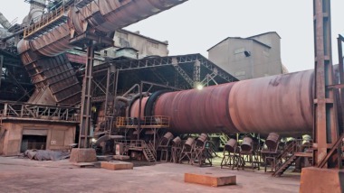
Within the framework of a modernization project at Wössingen cement plant, a new preheater tower and clinker cooler was constructed without interrupting plant operation. During a plant stoppage in spring 2009, this will be connected up to the existing infrastructure and put into operation. In order to keep the conveying distances between the new kiln line and the existing plant sections as short as possible, the new line had to be built close to the existing kiln. The confined space conditions demanded a somewhat unconventional approach to the construction work sequence. To enable accessibility during the construction work, it was necessary to first erect the new clinker cooler in a narrow gap between the existing Lepol kiln and the transformer station. It proved just as difficult to plan adequate free space for later accessibility to the system for maintenance work.
2 Decision for a new cooler
Conversion of a cement kiln line from the semi-dry to the dry process demands considerable modification of the process scheme and the plant technology. Conversion of the preheater to the precalcining technology requires an extension of the Lepol building as regards floorspace and height, frequently in the form of a structurally separate preheater tower. Due to the very limited accessibility to the burner building, conversion of the existing Recupol clinker cooler would have been similarly complex. Both building projects would have caused a plant stoppage of several months and unacceptable loss of production, while only a small number of plant components would have remained useable. Integration of a new preheater, kiln and clinker cooler into the existent factory infrastructure was therefore the more cost-effective option.
3 Technological concept and special features
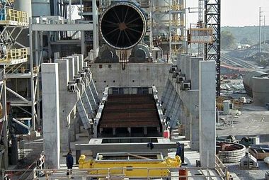
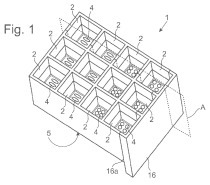
As a consequence of the confined space conditions (Fig. 1), a flexible cooler design with respect to length and width was needed. The installation location in a gap between existing structures prevented the use of a cooler with large standard modules that dictated the width. Lafarge Zement therefore decided to install an IKN pendulum grate cooler. This cooler type with KIDS (clinker inlet distribution system) configuration as a fixed inlet followed by a continuous grate area ensures low agitation of the clinker along its transportation distance, even in the case of a high length to width ratio.
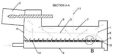
The grate plates for aeration of the bed of clinker are installed on grate support beams. Only every third row of grate plates is movable and responsible for the reciprocating motion for transportation of the clinker along the grate. Fixed and movable grate rows are mounted on different supporting structures. The supporting structure of the movable rows of grate plates is a connected, form-stable oscillating frame (Fig. 2), consisting of pendulum beams, oscillating beams and drive yoke. It is carried by the LPS (linear pendulum support) pendulum stations (Fig. 3), which are an integral part of the lower cooler housing. As the drive yoke is part of the oscillating frame unit, the grate can be driven by a single hydraulic cylinder.
The grate plate supports on the oscillating frame form the reference for alignment of the fixed grate plate supports. The oscillating frame is assembled during fabrication and the supporting surfaces for the grate support beams are machined in a subsequent work operation. Individual alignment of the non-movable rows of grate plates is provided by the design.
The LPS pendulum suspension is wear-free and ensures that the movement remains precise and quasi-linear throughout the lifetime of the machine. This fact permits tailoring of the reciprocation-movement gap to the geometry of the grate plates with their form-precise Coanda nozzle slots and thus assures uniform air distribution including cooling of the grate plates.
4 What spatial/logistical factors had to be considered?
The existing layout of the plant only left a narrow gap with a width of 12 m for the new cooler. Even this small space had first to be made available by demolishing a canteen building. Given an external cooler width of 4.5 m, there was very little space left for installing stairways, maintenance platforms, fans and auxiliary units of the clinker cooler – the plant designers faced the difficult challenge of optimally utilizing every square metre of the gap (Fig. 4).
The vertical reference point for the new kiln plant was defined by an old central cable tunnel, which ran just beneath the ground surface in the area of the planned clinker cooler. Because of the old installation installed in the vicinity, this tunnel could not be altered in any way. This made it impossible to use cellars and thus dictated that all building structures had to be above ground. The clinker cooler was thus built on a 3 m high steel platform in order to ensure that the clinker discharge end was high enough for an above-ground short-pan apron conveyor. The narrow construction area also dictated that other structures were built upwards and not sideways. For instance, kiln foundation #3 had to accommodate 3 cooler fans on two levels - the cooler drive hydraulic station that would normally be located in this area had to be placed on kiln foundation #2, which meant correspondingly extending its pipework. The remaining 4 cooler fans were positioned at an angle of 90° to the normal arrangement, in order to fit into a narrow space between the cooler and a transformer building. For later maintenance work these fans are only accessible from the burner platform by bridge crane - and that is only possible after the removal of several floor plates from the burner platform (Fig. 5).
The above-ground installation of all the machines and units means that there are no pits in the immediate vicinity of the preheater and cooler and the hazard potential in the case of an escape of hot meal is therefore greatly reduced.
5 Time sequence of the installation and integration into the overall plant concept
In August 2007, IKN received the contract from Lafarge Zement for the engineering and delivery of the clinker cooler, including kiln head and roll crusher. As the commissioning was planned for spring 2009, the schedule for the milestones was tight: presentation of the basic engineering for the construction planning in October 2007, foundation construction work in April 2008, delivery of all components by June 2008, preliminary and main assembly from July 2008.
German workshops were awarded the entire manufacturing scope for the most important functional components of the clinker cooler, such as oscillating frame, hydraulic drive and roll crusher. In the course of quality assurance, these components were also completely preassembled and tested, in order to exclude all assembly risks at the construction site.
In July the assembly work for the cooler commenced on schedule, parallel to the work on the preheater tower. First, the supporting structure (Fig. 4) was erected, then the lower cooler housing with the grate support shaft bearings went up step by step. After its acceptance testing and functional tests, the 3-roll roll crusher (Fig. 6) was transported by flat bed trailer as a complete machine to the construction site and was then simply lifted onto the prepared rails in the cooler without further assembly work being necessary. In the same way, the hydraulic power unit for driving the grate was delivered and mounted as a complete and function-tested unit, together with the PLC.
6 Challenges mastered
The basic engineering phase was characterized by intensive coordination between the partners in the project, which was essential in order to successfully deal with the demands imposed by building in an existing plant with confined space conditions. Special considerations in this phase were reducing the risks if hot meal escaped from the system, providing adequate access for inspection and maintenance purposes, safeguarding the existing infrastructure and the use of a steel platform (Fig. 7) to minimize the foundation and concreting work for the installation of the new pendulum grate cooler. The cooler components were delivered on schedule and the troublefree site assembly phase attested to the intensive planning work. Thanks to the functional tests performed prior to dispatch, the cold startup took place according to plan without any incidents and as of today, all the preparations have been made for a problem-free hot startup at the end of the 1st quarter of 2009.
www.ikn.eu