Energy gained by downhill limestone transport
1 Introduction
It is well known that the efficient connection with raw material deposits is of vital importance for a cement plant. Therefore, reliable and cost-efficient technical solutions are a necessity for the success of every cement plant. In the past, limestone was often transported by truck which meant both high cost and environmental pollution. Today, continuous conveyors are acknowledged world-wide as a cost-efficient alternative [1]. When dimensioned properly, they adapt ideally to the topographical conditions on site and have a number of advantages over the transport by truck, such as for example:
High conveying capacity with minimum space requirements
Low construction cost for conveyor routing even under difficult topographic conditions
Low energy consumption when compared to limestone transport by truck
Low personnel requirements
Optimal adaptation capabilities to the ambient conditions on site, minimizing environmental impact
Low noise emission
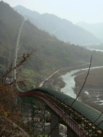
In many cases the exploitation of new limestone deposits is only made possible by using belt conveyors with horizontal curves. One main reason is that these conveyors offer considerable advantages in satisfying environmental concerns and requirements for official permits. Ciments Vigier SA in Reuchenette near Bienne/Switzerland faced challenging routing conditions of a belt conveyor system with horizontal curves after deciding to exploit their newly opened “Tscharner” quarry, which is situated around 2 km to the west of the plant.
The special characteristic of this continuous conveying system is mainly that it links a limestone deposit situated on a hill with the cement plant situated in a valley, therefore forcing the conveying route to be nearly completely descending. The special features of the descending material transport and the sophisticated drive concept, as well as the level of technology in the field of continuous conveyors with horizontal curves, which have been realized in this project, will be presented in the course of this article.
2 Requirements on the belt conveyor system
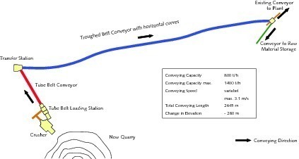
As shown in Figure 1 the crusher in the quarry was to be linked by a conveying system to the cement plant situated downhill. During transport a difference in height of 280 m in total at an inclination of up to 28 degrees had to be overcome. Right from the beginning the goal was to minimize, as far as possible, the number of conveyors and thus the number of transfer stations. Furthermore, a tunnel designed for limestone transport by truck was to be used as the route for the conveying system to be constructed.
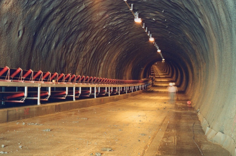
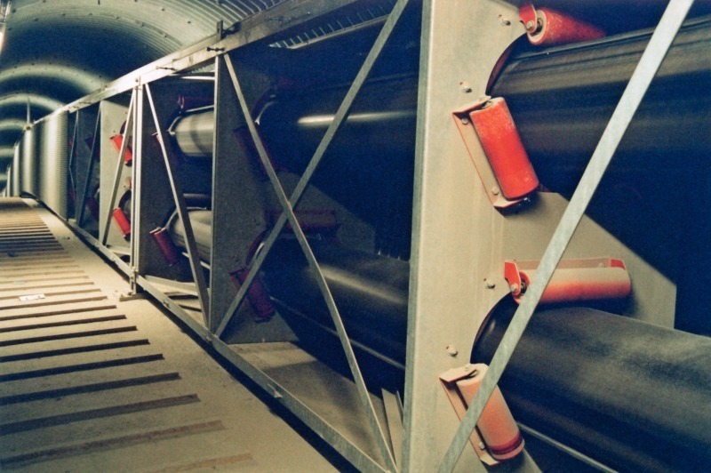
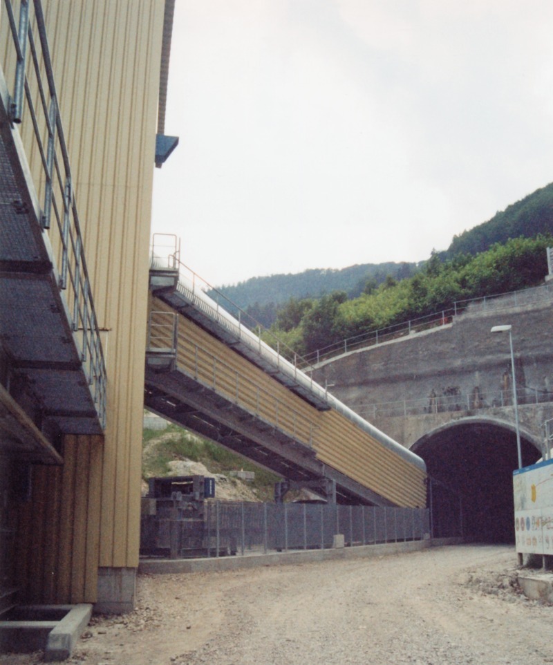
Further basic requirements taken into consideration while realizing the project, were both a high reliability of the total system at greatly varying operation conditions and the use of the energy produced by the operation of the descending continuous conveying system. As Figure 1 shows, Beumer met these requirements by combining a tubular belt conveyor in the first section of the transport route with a troughed belt conveyor with horizontal curves in the section running through the tunnel. The use of a tubular belt conveyor makes it possible to handle a conveying capacity of up to 1400 t/h, even when declining up to 28 degrees. This closed conveying system is especially suited for this kind of descending conveying lines. The downstream troughed belt conveyor adapts ideally to the tunnel wall on the whole conveying route and therefore is the optimal solution in combination with the travel and service track within the tunnel (Fig. 2).
3 Description of the complete system
As seen in Figure 1, about 2645 m of conveying route must be surmounted from the crusher to the transfer station of the downstream conveyor within the cement plant. An average conveying capacity of 800 t/h of limestone is to be taken into account with peak values of up to 1400 t/h which mainly determined the dimensioning of the conveyors.
3.1 Tubular belt conveyor system
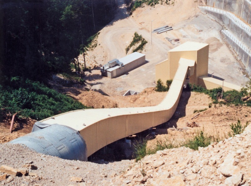
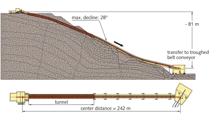
Extreme topographical conditions had to be taken into consideration in the design of the first section from the quarry down to the intermediate valley below it. As illustrated in Figures 3 and 4, a difference in elevation of 81 m on a length of only 242 m had to be overcome (Fig. 5). Tubular belt conveyors are especially suited for this kind of application since they are distinguished by the following advantages [2]:
An exceptionally good ability to negotiate curves and thus an extreme adaptability to the ground profile,
Good sealing and thus a nearly dust-free transport of limestone due to the closed conveyor system of the tubular belt conveyor,
Realization of large angles of incline/decline thanks to the material support within the closed tubular belt
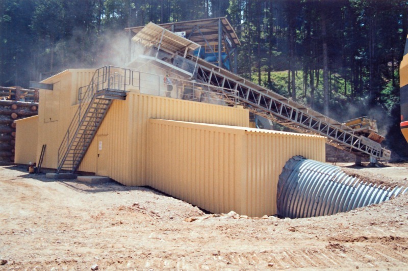
The material is fed by a short troughed belt conveyor directly from the crusher to the tubular belt conveyor at an angle of 12 degrees. Immediately after the feed, the belt is formed into a tube with a nominal diameter of 400 mm.
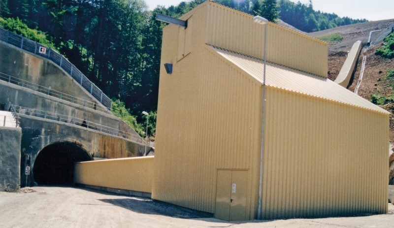
As shown in Figure 3, the tubular belt conveyor enters a tunnel of a length of approximately 100 m cutting a hill top immediately behind the tube forming section. A look into the interior of the tunnel (Fig. 6) shows that, thanks to the compact design of the tubular belt conveyor, it was possible to install a maintenance footbridge ensuring free access to the system despite the small tunnel diameter of only 3140 mm.
After having left the tunnel, the tubular belt conveyor adapts ideally to the ground profile. A maximum decline of 28 degrees is reached in this area. The conveying route is equipped with three vertical curves with radii of 120 m to adapt to the ground.
At the end of its 242 m long route, the tubular belt is opened in the tube opening section to form a trough and the limestone is transferred to the downstream troughed belt conveyor with horizontal curves.
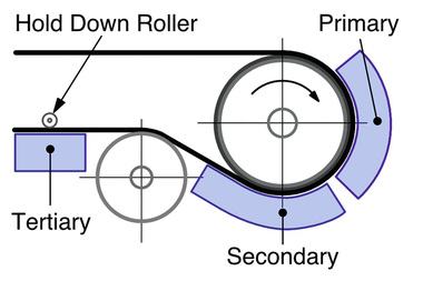
Since proper handling of the belt significantly increases its useful life, the design of the tube forming section is of utmost importance. While the belt is formed into a tube on a length adapted to the particular belt, both edges of the belt are guided by sets of idlers and finger rollers to create an optimum overlap at the end of the tube-forming area. Moreover, a trouble-free operation is ensured by monitoring of the proper shape and filling level of the tube.
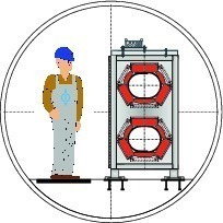
To negotiate the conveying route, the idlers provided for supporting the belt are mounted to the idler fastening plates used as supporting elements in the conveyor. As shown in Figure 7, the idlers shape the tube into an oval cross section. Aside from the better belt tracking features thanks to the level supporting surface in the bottom area, this cross section improves the “seal-effect” of the belt edges and, as a result, the tightness of the system. Each idler station consists of six idlers, three mounted on each side of the bulkhead plate. This design eliminates the gap between idlers and avoids wear and tear, as well as damage to the belt edges. This ensures that, if the belt tracks off, the belt edge is guided while running onto the next idler and does not touch the end wall of this idler.
The conveyor belt itself consists of components which have long proven their reliability and suitability for belt conveyors. The traction elements in the belt are arranged to allow for proper belt closing and overlap as well as for an even distribution of the belt tension of the oval shape of the belt cross section.
Thanks to the intelligent design of the conveyor frame and the arrangement of the idler bulkhead plates it is possible to use the conveyor frame as a load carrying element in bridge areas of the steel structure. Therefore, the weight and cost of the required steel structure can be reduced.
3.2 Troughed belt conveyor system
with horizontal curves
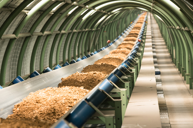
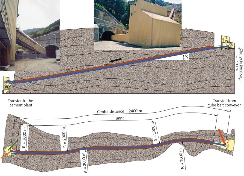
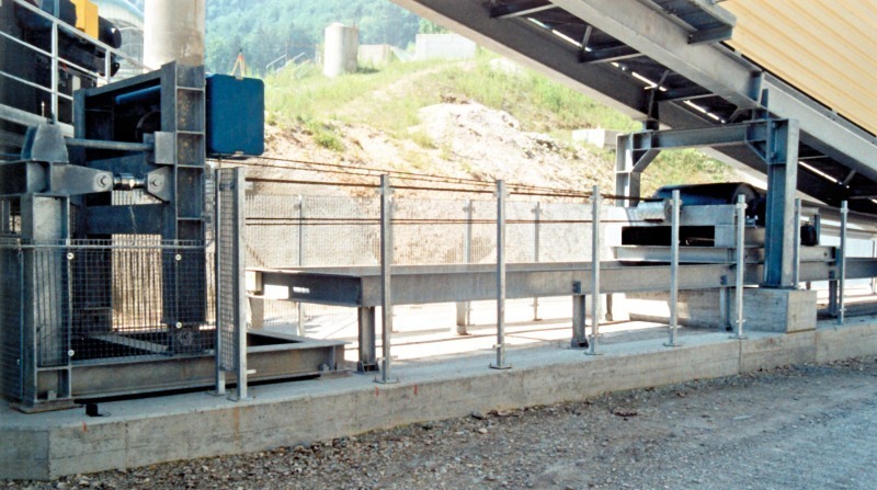
As already mentioned, the troughed belt conveyor system with curves and a length of approximately 2.4 km was integrated into a service and transport tunnel on a length of more than 2 km. As shown in Figures 8 and 9, the tunnel has a downward slope of approximately 5 degrees due to geological conditions.
Within the tunnel, the curved conveyor system was positioned along the right tunnel wall in conveying direction so as to have sufficient space for the travel and service track. The troughed belt conveyor with horizontal and vertical curves was designed with a belt width of 1200 mm because of the maximum conveying capacity of 1400 t/h. As illustrated by the technical data in Figure 10, the troughed belt conveyor with a length of 2400 m allows for a difference in elevation of 193 m. Furthermore, five horizontal and three vertical curves were required for optimal adaptation of the conveyor to the routing of the tunnel.
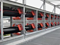
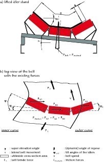
A belt conveyor is curved by adjusting position, angle and pitch of the idlers of each idler station (Fig. 11) on the basis of careful calculation, thus ensuring a precisely guided movement of the belt during the possible operating conditions. Beumer has developed a comprehensive calculation and simulation program to calculate and design belt conveyor curves. Besides the theoretical foundations, the wide experience [1, 3, 4, 5] and knowledge gained through the design and optimization of numerous conveying systems since the 60’s are integrated into these calculations.
These calculating principles allow determination of all parameters for an optimum positioning and adjustment of the idlers all over the system. Variable parameters, such as the coefficient of friction between idler and belt, belt impression rolling resistance, etc., are taken into account for these calculations. The calculation is accompanied by a simulation of all theoretical and practical operating and loading conditions, including stationary operation, start-up and shut-down under worst-case conditions. Special attention had to be given to the stopping of this descending system in emergency situations – e.g. in case of a power failure at partial loading conditions – to ensure proper belt travel by correctly combining the idler adjustments with the drive and brake concept.
The drive and take-up concept chosen, which was used for both the tubular belt conveyor and the troughed belt conveyor with horizontal curves, will be presented in the following chapter.
4 Take-up and drive concept of the system
Dimensioning the take-up and drive system and defining the control logic, starting from the customers’ requirements of reliability and profitability, are based especially on the calculation of the complete system explained above.
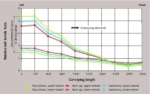
The diagram in Figure 12 shows the calculated belt tensile force in the upper and lower strand over the entire length of the system. The diagram clarifies the circumferential forces of the troughed belt conveyor with curves in the conditions of start-up, shut-down and stationary operation. The goal of these calculations is to minimize the resulting belt tensile forces through the application of the appropriate drive and take-up system, while at the same time maintaining the belt forces necessary to transmit the required drive power in both driven (generator) as well as driving operation.
Therefore a distributed drive concept was chosen, combined with a take-up system according to the principle of a “constant center distance”.
4.1 Drive concept of the belt conveyor
Due to the requirements of the drive and take-up system of the troughed belt conveyor, the transmitted circumferential forces were distributed to two drive pulleys at the loading station of the system. Moreover the drive pulley located in the front in the conveying direction was equipped with two drive units.
Since the user, in an effort to reduce the spare parts stock, requested the use of identical machine components, the drive units used for the troughed and the tubular belt conveyor were of the same design. Thus, the tubular belt conveyor was equipped with one drive pulley and two drive units at the loading station.
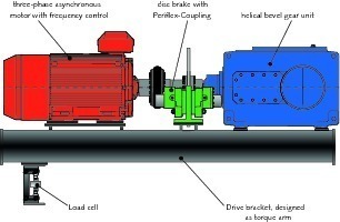
These drive units shown in Figure 13 consist of a three-phase asynchronous motor with frequency control, a shaft-mounted helical bevel gear unit and a disc brake on the input side of the gear unit. The drive platforms are supported by a load cell used to determine the drive torque. Besides its function as a mere holding brake, the disc brake is also used for stopping the system in emergency situations, e.g. in case of a power failure.
The motors which have a nominal capacity of 160 kW each, and which are used both for driven and driving operation can be regulated over a wide range. This ensures optimal load distribution on the individual drive units for different operating conditions. Therefore, the load is the same for all drive units in stationary operation, compensating for expansion slippage. The same applies, for example, if the drive units run at slightly different speeds due to build-up or wear and tear of the drive pulley lagging. Furthermore, using a frequency converter ensures an optimum system behavior during start-up. As regards the safe guiding of the belt in horizontal curves as well as the limitation of the maximum belt tensile forces, the circumferential forces of the pulley must not exceed certain values during start-up.
The circumferential forces mainly depend on the drive power demand during stationary operation of the conveyor, which again is influenced decisively by the load distribution along the conveyor. Therefore, a drive strategy had to be used which takes the system length, the belt tensioning system, and the routing of the system into account. The start-up and shut-down program [6], developed by Beumer especially for these cases of application, ensures that the required torque is always produced according to a set curve depending on the operating condition, and that the transitions to the stationary operation are always smooth without abrupt alterations. By these measures, the additional dynamic stress on the belt could be reduced to a minimum.
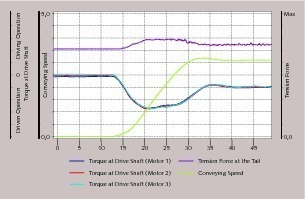
Figure 14 shows graphs of measured torque, conveying speed and belt tension of the troughed belt conveyor loaded continuously during such a start-up process. It is clearly visible that, due to the defined torque curves and although the take-up station is located at a distance of approximately 2.4 km from the point of force introduction and the introduced force is transported to this point by the belt, which is relatively elastic, the course of the tension force does not show any abrupt alterations.
4.2 Emergency stop principle
A special feature of these systems is the driving operation with continuous load. The gained electric power of approximately 350 kW is transferred to the mains by the means of an energy recovery unit, thus reducing to a considerable extent the cost of energy of the complete system.
The driven operation of the system requires a special shut-down concept in emergency situations such as power failure. As in such situations the drive motors would not be able to stop the system in a guided manner, a second, redundant unit was mounted for the purpose of stopping the system. The torque transmitted by the drive motors is measured by load cells under the drive platform designed as swing bases and is directly transferred to the brake unit. In case of a power failure, the brake unit generates a torque depending on this measured value, shutting down the system within the required time of 20 seconds. Thus it is ensured that an overload of the system and especially of the belt is avoided even in such emergency situations.
4.3 Take-up system
In order to adjust the tension of the belts of both systems the principle of a “constant center distance” was applied. This means that a take-up carriage with take-up pulley is moved horizontally by an electric winch so as to adjust the required pretension (Fig. 15). The existing pretension is measured before each start-up of the system by integrated load cells, compared to the setpoint value and corrected automatically, if required. Since in this take-up system the pretension and the drive power directly correlate the existing pretension is compared to the setpoint value which depends on the drive power. This way excessively high or low belt tensile forces, e.g. due to strong belt expansions caused by temperature, can be compensated. If the actual pretension during stationary operation should be outside the setpoint value range, an intervention from outside is carried out by an automatic control and monitoring system at a defined load condition.
5 First practical experience
After an installation and commissioning period of less than 10 months, the limestone transport system was handed over to the user, and the exploitation of the quarry could start. This was possible despite the difficult installation conditions mainly because the commissioning phase of the complete system could be completed in only four weeks thanks to the comprehensive operational simulations of the belt conveyor systems which were carried out beforehand.
The calculated design and dimensioning of the system was fully confirmed by the tests carried out during the commissioning and test phase, especially those simulating extreme situations (emergency stop in case of power failure, varying loading conditions, etc.). The data recorded such as belt tensile forces, braking torque and speed prove in an impressive way that there were no excessively high belt tensile forces or speed alterations in either of the operating conditions. More-over it could be demonstrated that the redundant stopping unit chosen was able to stop the system reliably in emergency situations with a braking torque depending on the respective loading condition.
6 Closing remarks
The reliable connection of the “Tscharner” limestone quarry with Ciment Vigier’s plant was only possible by an optimal combination of tubular and troughed belt conveyor systems with curves and an intelligent drive concept. This article shows once again that innovative belt conveyor solutions are able to offer plant operators the ideal platform for reliable and cost-efficient production. Thus, the success is founded on integrated, state-of-the-art engineering for current and future technology challenges as faced by many cement plants worldwide.