To ensure the safety of burn processes in the industrial sector of heat gain or power supply the selection of varied fuels becomes more and more important. The usual storage and containment of such materials are within silos. When deciding on the storage type, consideration must be taken regarding the explosion protection of such equipment taking into account suitable regulation and control.
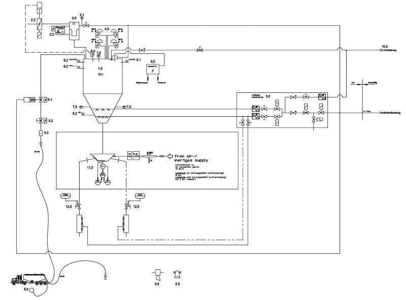
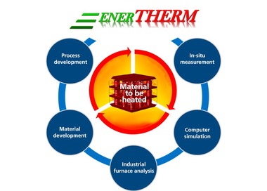
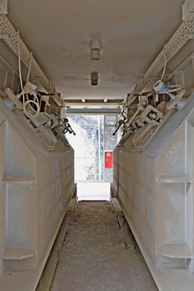
Dust explosions are serious and represent danger. The presence of combustible dust air mixtures in different areas of the plant give the potential for an explosion to occur and need to be avoided. Apart from constructive explosion protection equipment and pressure resistant construction methods in accordance with VDI guideline 3673, technical measuring and control equipment is necessary for the safe operation of a storage silo (Fig. 1). These are especially required for:
CO, CH4 and O2 analyser systems with certified measuring function
Temperature sensors
Continuously level measurement
Level sensors
Pressure sensors
Filter with clean gas flap
Explosion doors with limit switches
Enclosure at the silo discharge system
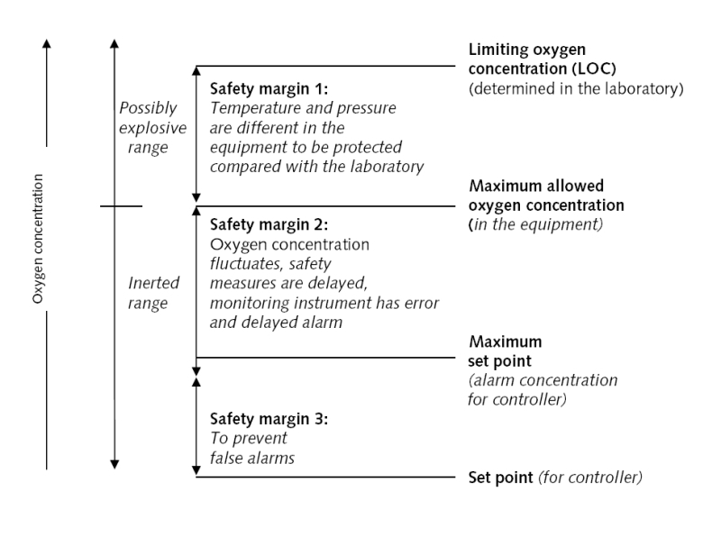
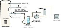
The detection of smouldering fires will be carried out mainly with CO and CH4 analyser systems. Historically, oxygen-measuring instruments were not used in practicable silo plants which supervise and guarantee the inerting procedure. According to the guidelines (e.g. TRBS 2152, VDI 2263, CEN 15281) it is necessary in dangerous situations to maintain and supervise the limiting oxygen concentration (LOC) for different fuels. One method for application of monitoring and control systems is shown in Figure 2.
Electrical control problems for preventive explosion protection and process monitoring
The task is the installation of an automatic central control system that guarantees the inert atmosphere during chemical and physical processes. The function of operation, monitoring and control has to be carried out automatically or manually with a process computer or equivalent equipment. The following important equipment has to be implemented:
A: Gas analyser systems
B: Temperature sensors
C: Inerting systems
D: Valves and flaps
A: Gas analyser systems
The control unit (RSC – robecco secure center®) compares the signals of the gas analyser system (digital values and analog values) of the process with the given security concept. With help of the measured gas components necessary alarms will be generated to guarantee the inert atmosphere. Furthermore the operability of the gas analyser system is supervised. The following parameters are observed:
Temperature min. at sample probe
Function of pump
Function of nominal and actual values
Humidity of the sampled gas before analysing
Flow control of the complete gas sampling and conditioning system
Display of the current gas flow paths (at sequential measurement)
Auto calibration or manual calibration of the analyser system or the measuring instrument
Disturbances in the analyser
Obtaining of the max. value of the analyser
Obtaining of the max.-max. value of the analyser
Supervising of the analog measuring
B: Temperature sensors
The control unit (RSC) compares the signals of the temperature sensors (digital values and analog values) of the process with the given security concept. With the help of the measured gas components and temperatures the controller generates special behaviour conditions, which are based on the limiting oxygen concentration (LOC), which is given by the explosion protection concept. If the temperature is changing in the system the LOC will be automatically adapted and the alarm values will be changed accordingly.
C: Inerting systems
With help of the generated signals of the gas analyser system and the temperature sensors the controlling (RSC) controls the inerting system. With alarms generated within certain aggregates range, valves of the inerting plant will be opened so that the necessary inert gas quantity will be dosed. After the inerting process the range valves will be automatically closed. The control unit observes the process and confirms a successful inerting process. If the process was not successful, the procedure will be repeated. Additionally, robecco secure center supervises the inerting plant and examines the ready status. The following parameters are observed:
Storage gas (CO2, N2) min. und max. (weight or pressure, depending of the kind of gas)
Pressure minimum and maximum
Pressure analogue
Flow control of the inert gas out of the inerting system
Vessel heaters or pressure up heaters
Cooling unit (if necessary)
Range valves
Dosing of the gas volume for each range valve
D: Valves and flaps
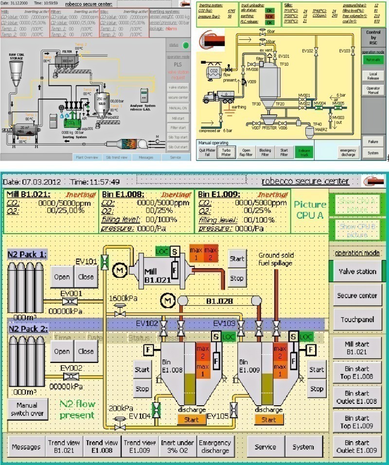
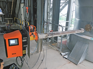
The control unit (RSC; Fig. 3) has to send signals to the Central Control Room (CCR) of the process according to the safety concept to control valves and flaps. With this function the dangerous process will be closed against other process aggregates and explosive atmospheres will be blown out of the process.
Conclusions
The adjustment of the oxygen and carbon monoxide limit concentrations in relation to the process temperature is necessary. The evaluation of the measured values and an alignment with typical trial processes are guaranteed. This makes operating reactions possible, e.g. sealing of leakages or prevention of a further entry of oxygen into silos and aggregates.
A safe switching over of the silo plant from “automatic mode” to “manual mode” during process conditions, like test run, maintenance, revision to avoid accidents must be guaranteed.
Controls must be able to take over self-sufficient system functions in case of failure situations of master systems:
The monitoring of all system-relevant functions of the sensor system and the inerting plant with dosing station is necessary. An accurate inert gas dosing regarding effectiveness and environment must be considered. Maintaining the existing inert gas stock and the future procurement of storage must be considered.
The functionality of the components has to be supervised, relevant errors or failures must be signalled to alarms. The automatic determination of the maintenance intervals, the maintenance dates and maintenance work of individual components in dependence the actual working time and operating frequency guarantees operability and with this a safe and productive process.