Mechanical and physical properties of chalk and impacts on mining operations and slope designs

Chalk occurs in northern Europe from the southern UK to eastwards deep into Russia. It is exploited as an industrial mineral for a large variety of uses. From the examples of three different chalk mining operations, it is shown that although geologically and geochemically quite similar, all three deposits have very different physical and geomechanical properties which in turn have impacts on slope designs as well as mining methods, mine planning and equipment selection.
1 Introduction
Chalk occurs in northern Europe from the southern UK and northern France to Germany, Denmark, Poland, Ukraine and into Russia. It is exploited as an industrial mineral for a large variety of uses, for example, the lime and cement industry.
This paper focusses on the material properties of three different chalk mining operations. Although geochemically quite similar, with high CaO-contents, all three deposits have very different physical and geomechanical properties which, in turn, have impacts on slope designs as well as mining methods, mine planning and equipment selection.
2 Chalk deposits
2.1 Obourg, Belgium
The Obourg deposit is located in the Mons Basin. The mined formations are Cretaceous materials of the Santonian and Campanian stages [2]. Regarding geological structures, [9] mapped the geological structures and concluded that the deposit is dipping south at an angle of 12°. Some sub-vertical, north–south-striking faults were identified. The mapped joints have a wide scatter and could not be allocated to distinct joint sets.
The southern limit of the currently mined Quarry 3 is only 120 m from the Canal du Centre, an important public waterway large enough for shipping. Therefore, the groundwater is not lowered by pumping. Chalk is extracted partly above the waterline and the majority is dredged from below the waterline.
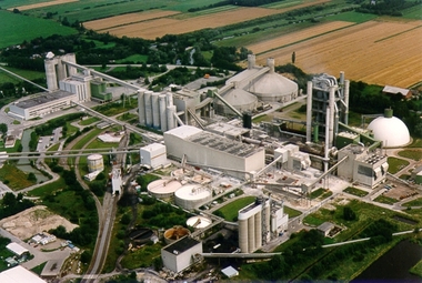
2.2 Lägerdorf, Germany
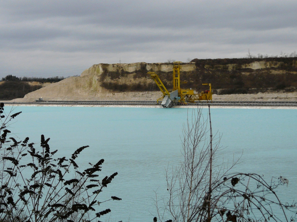
The chalk deposit around Lägerdorf in northern Germany is also Cretaceous material (Figure 1a). While the topography is relatively flat terrain, the underlying deposit is situated on top of a salt dome which lifted the entire chalk formation to the surface and exposed material from the Conacian to the Maastrichtian stages [5]. The culmination point is just under the town of Lägerdorf and, due to the uplift of the deposit, is dipping in the active mining areas west of Lägerdorf at 5-7° towards the northwest, while east of Lägerdorf the formations are dipping 5-7° towards the southeast.
The natural groundwater level in the area is only 3-4 m below ground and even less in marshy areas. Mining is long ongoing at this site and was traditionally carried out in dry conditions by drawing down the natural groundwater table. Today, the active mining area to the west of the town consists of a series of three adjoining pits (east to west):
1. The oldest and deepest pit is the pit Schinkel. It was mined down to 120 m depth and is currently used for water retention and as a pumping sump before eventual discharge from the mining area. The groundwater level is drawn down around the pit Schinkel by approximately 70 m. This results in a 40-50 m deep lake or sump for retention
2. The pit Alte Heidestrasse, northwest of pit Schinkel, is currently mined down to maximum 110 m depth. Groundwater is drawn down by approximately 95 m below ground level and is thus lower than the adjoining pit Schinkel. Mining is carried out in dry conditions. The bottom is flooded and used as a sump. The water from there is pumped over to the inactive pit Schinkel and later discharged
3. Further to the northwest is the newest pit Neue Heidestrasse. This is currently 55 m deep and this is still located above the drawdown cone of pit Schinkel and dry mining conditions are thus encountered. Rainwater and minor amounts of groundwater are routed to the Alte Heidestrasse pit by means of open channels
There are two more pits east of the town of Lägerdorf:
1. The currently dormant pit Saturn, which is 55 m deep and the groundwater is constantly drawn down to that level
2. The yet undeveloped extension area Moorwiese, where most of the recent tests and exploration works were carried out
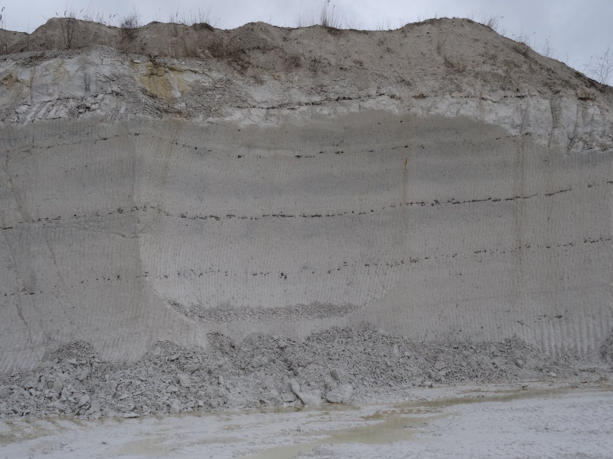
With regard to geological structures, faults are observed but the displacement is in the range of a few metres and not relevant for the mining operation. While the bedding planes can be followed over tens of metres in the faces, jointing is intense but of low persistence. Several bedding-parallel flint layers (or chert or silex) can be observed and are used as marker horizons (Figure 1b). The flint is usually fist-sized but can have sizes of up to 30 cm. The chalk itself is chemically rather homogenous but the upper 20-40 m are visibly more weathered and are mechanically weaker than the lower layers. This is probably a weathering effect of the regional groundwater flows over time.
Due to the dip of the formations and the rather flat topography, the overburden–consisting of fluvioglacial sediments such as sands, gravels, silts and clays–is increasing in thickness at a further distance away from the underlying salt dome.
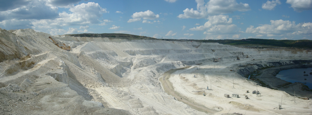
2.3 Volsk, Russia
The deposit is located about 650 m north of the Volga River in the Saratov region (Figure 2). The Cretaceous deposit consists of clays of the Albanian stage, overlain by chalks of the Touronian to Maastrichtian stage and diatomite overburden. All materials are being extracted. The natural groundwater level is within the underlying clays and above the level of the Volga river.
The deposit structure is a monocline dipping 9–14° towards the west. [7] indicates that the deposit may be a complex system of listric faults and ancient paleo-landslides, and also noted the presence of karst features within the chalk.
3 Material properties
The material properties were determined during several investigation campaigns at Obourg [2, 3], Lägerdorf [1, 5] and Volsk [8, 10] and are shown in Tables 1 and 2.
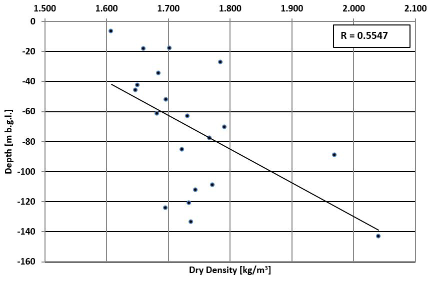
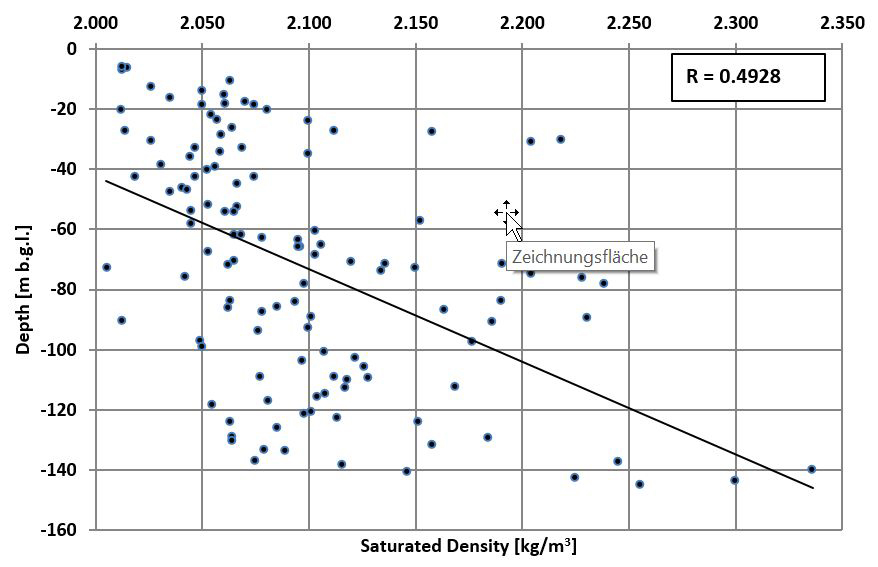
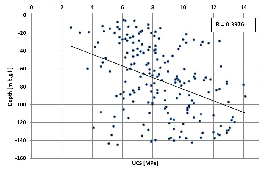
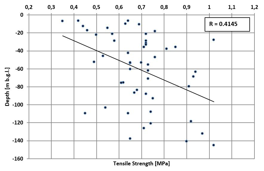
Although all three deposits are of similar geological age, the variations of the material properties are significant. The greatest number of tests were carried out in 2019 on the Obourg materials. [2] carried out a very high number of tests along three drill holes with a total length of 375 m (100 saturated densities, 20 dry densities, 200 unconfined compressive strength tests (UCS), half with Young’s modulus determination, and 45 Brazilian tensile strength tests (BTS)). They concluded that saturated as well as dry density increases with depth, likely due to a reduction of porosity (Figure 3). Also, the UCS increases with increased depth, while the tensile strength does not seem to follow such a trend (Figure 4). However, all linear correlations presented in Figures 3 and 4 are not very robust with low correlation coefficients between 0.39 and 0.55. It has to be noted that although there are a large number of test results, especially for the UCS, these originate from only three drill holes, and minor local variations may have an influence on the test results.
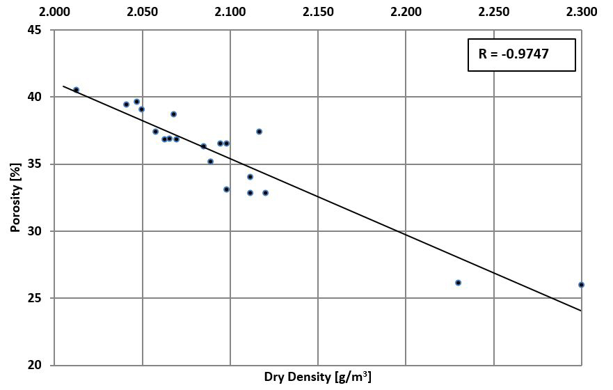
There is a good correlation between the porosity and the dry density (Figure 5). Since there is also an increase of the densities at deeper levels, the increase in density and decrease in porosity are likely to be a result of consolidation at higher overlying stresses.
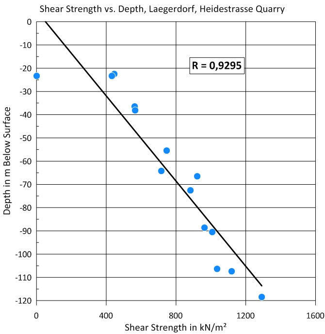
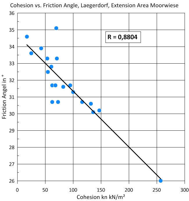
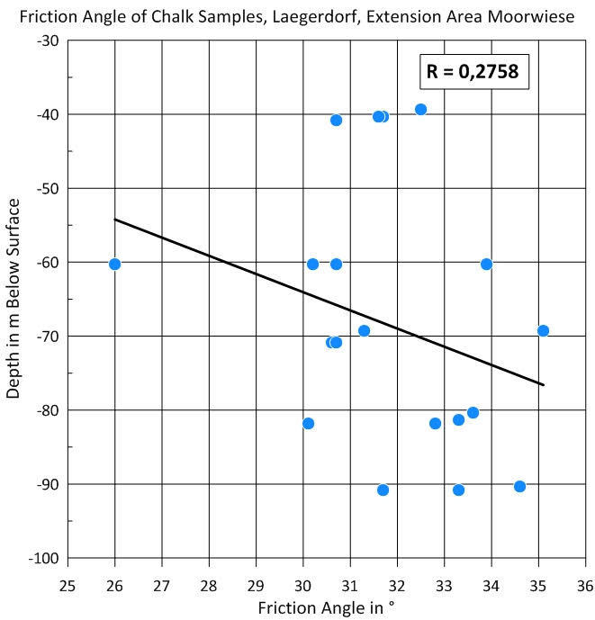
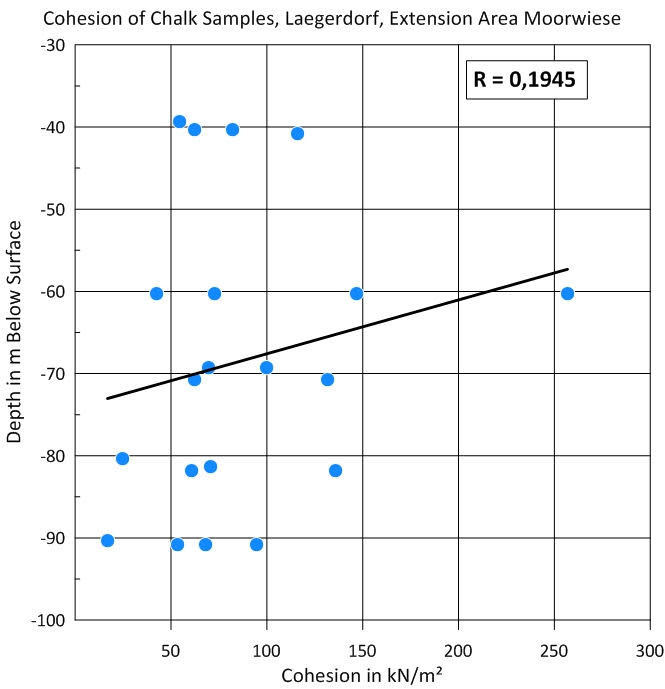
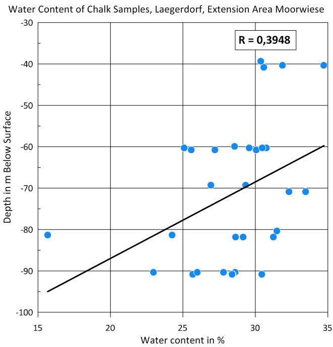
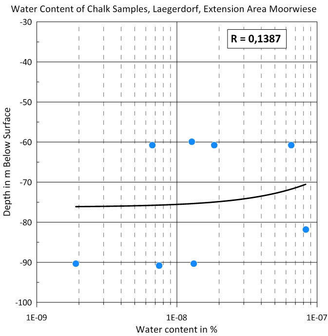
At Lägerdorf, the increased shear strength could be correlated with increasing depth for the western pits Heidestrasse (Figure 6a). Also, a correlation between cohesion and angle of friction was observed in the eastern deposit Moorwiese (Figure 6b). Both correlations are highly significant, as the correlation coefficients (R) show. However, no correlations of angle of friction, cohesion, porosity or permeability could be determined with increasing depth (Figure 7), which is proven by the low correlation coefficients.
In the area of the Moorwiese extension, a lot of investigations have been carried out based on cone penetration tests (CPT) to evaluate the depth and the intensity of the weathering zone on top of the chalk strata. The intense weathering is based on chemical weathering of the soluble CaCO3 (which comprises more than 90 % of the chalk) as well as on the impact of deep frost during the colder parts of the Pleistocene.
Weathering seems to reduce the shear strength of the chalk significantly. Decomposition of the primary structure increases with decreasing depth leading to the transformation of the chalk into a kind of coarse-grained angular shaped soft rock near the surface. CPTs have shown an increase of strength from the surface layers down to depths of between 15 m and nearly 30 m below surface. At these depths, the strength reaches that of the above-mentioned unweathered chalk asymptotically. This strength reduction leads to the necessity to maintain lower slope angles in these upper layers.
Furthermore, hydraulic testing in this area resulted in the conclusions that these weathering processes on top of the chalk layers also lead to a significant increase in hydraulic conductivity.
Shear strength along joints and fissures was estimated using direct shear tests. Since no sample for actual joint shear strength testing could be obtained for these tests, the chalk sample was forced into failure first. The horizontal joint that has been created by the first step of the shear test was then exposed to further shear force to determine friction angle and cohesion. This was done successively several times for extended movements. These tests show clearly:
1. The effective friction angle is not influenced by increasing displacement. It varies only slightly around a mean value of 33°
2. The effective cohesion decreases significantly with increasing displacement. Initially, the mean value of cohesion is 102 kN/m2. It is reduced to an average value of 38 kN/m2 near the end of the tests and then further down to less than 5 kN/m2 at the minimum. It can be expected that cohesion disappears completely after displacement values higher than tested
This leads to the conclusion that the geometry of joints and bedding planes has to be taken into consideration in calculating slope stability.
4 Slope designs
The operational and final slope designs of the three operations are very different (Table 3). They are a result of the individual mining method, the material parameters and groundwater conditions.
4.1 Obourg slope designs
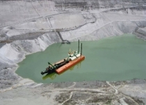
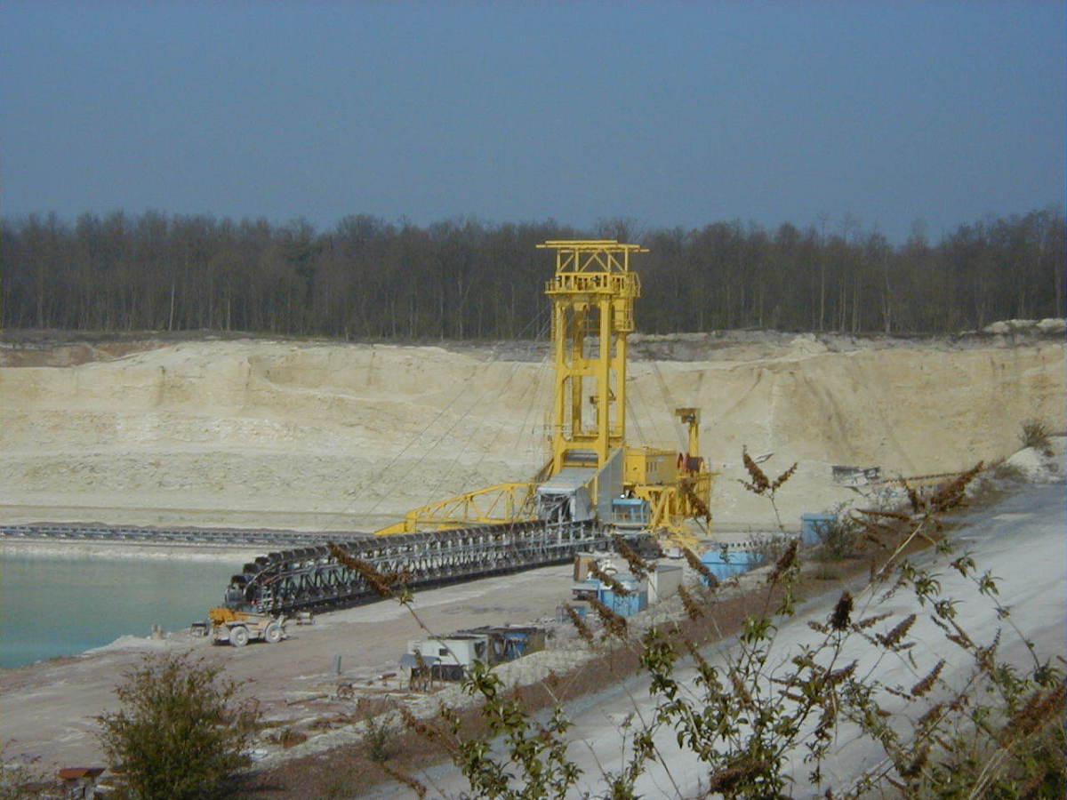
The deposit at Obourg is close to a major public canal which presents a major shipping lane. The operators decided not to drain the pit and work in dry conditions, but to extract the majority of the material below groundwater level by means of a dredging operation with a bucket chain excavator (Figure 8). The excavator can reach down to a maximum of 50 m below ground and extract the chalk at an even overall slope angle of 46°. The minor part of the deposit above the groundwater level is mined directly by backhoe excavators. No slope failures were reported, however, since most of the slope is submerged, slope failures would not be obvious. Today the slope design is not geotechnically optimised for maximum chalk recovery but is merely a result of the mining method and constraints. [9] assessed the possibility to steepen the slope angle and to optimise the chalk recovery and determined that overall slope angles of 65-70° are possible.
4.2 Lägerdorf slope designs
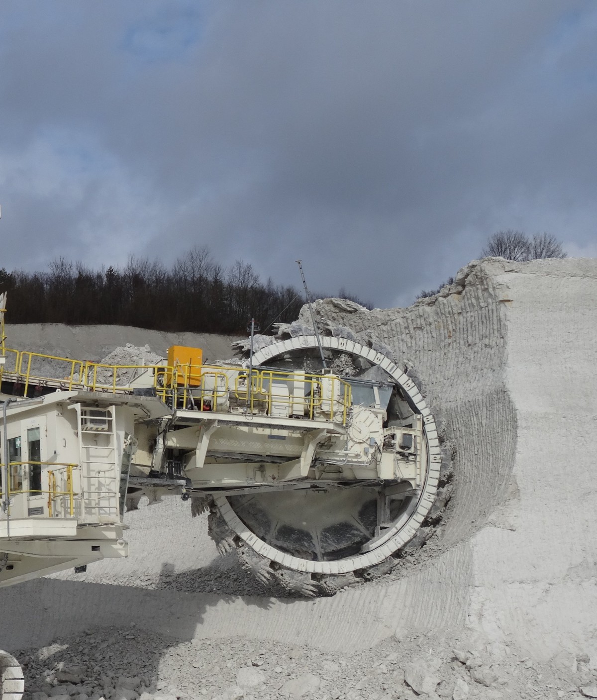
At Lägerdorf, the operation is draining the actual pits to work in dry conditions. The water is drained by gravity to the lowest point of the mining area at pit Schinkel and discharged after passing a settling facility.
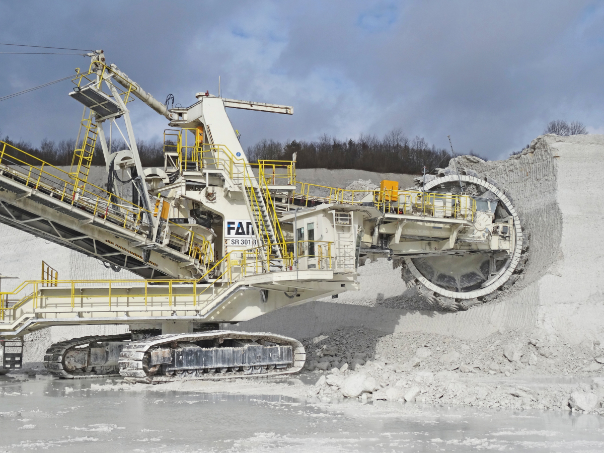
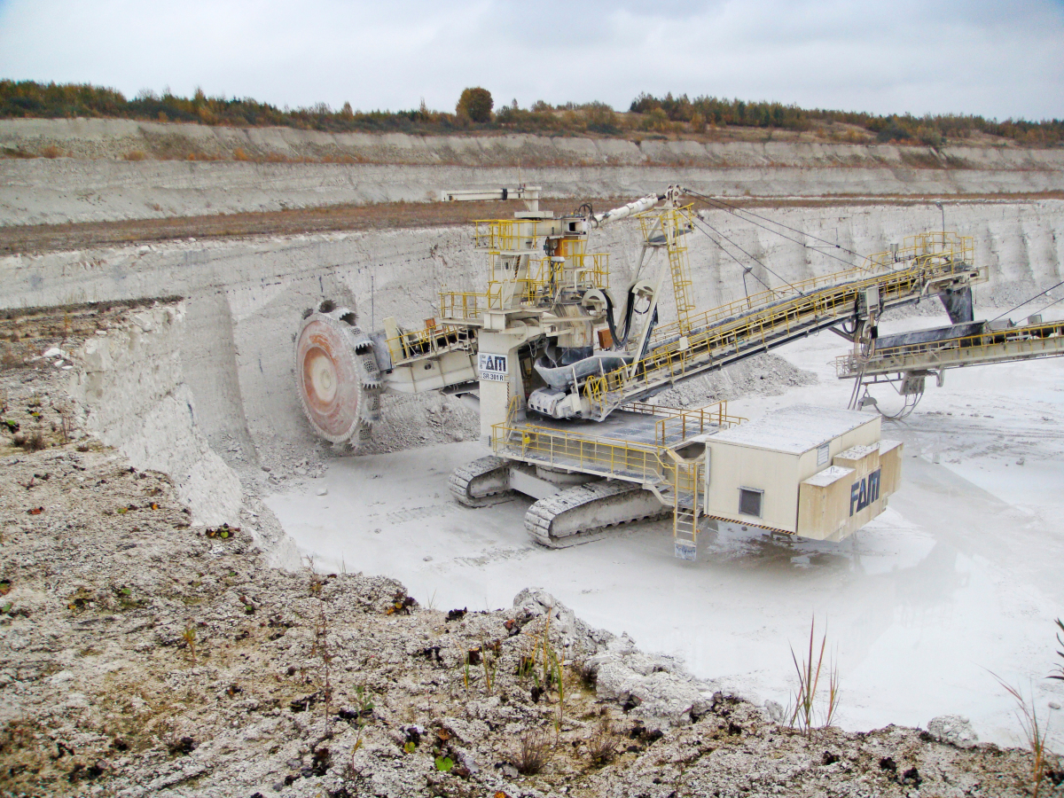
The final slope design for the current mining area Neue Heidestrasse foresees eight benches in chalk of 11 m height each, resulting in an overall final slope height of 88 m and an overall slope angle of 60°. The extraction equipment is a bucket-wheel excavator (BWE) (Figure 9).
The dip of the formation is gentle and favor-able for the mining and slope directions. Wedge formation is locally possible. The persistence of the jointing is too low to be relevant, but unfavourable intersection of bedding and faulting can form locally unstable blocks. However, due to the weak rock mass properties, the principle identified failure mode is by exceeding the material rock mass shear strength. Being a ‘weak rock’, the slope design process followed the process of defining the overall slope angle first (60°) and fitting the benches into this overall slope angle. In the weathering zone on top of the deposit, the slope angles are reduced to 45° in the lower half and less than 25° in the upper half as well as in the overburden. The bench height and the bench face angle is a result of the dimensions and cutting action of the BWE’s cutting wheel and not of the bench material properties or geological structures.
On an overall slope scale, the older pits, Schinkel and Alte Heidestrasse, were mined deeper in the same material and show no large-scale instability issues. Minor localised slope failures, however, have happened in the past, principally in the upper parts of the slope in the mentioned weathered part of the chalk.
4.3 Volsk slope designs
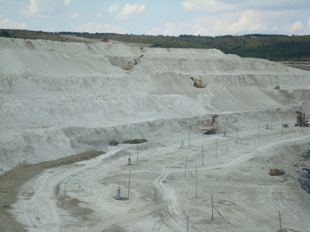
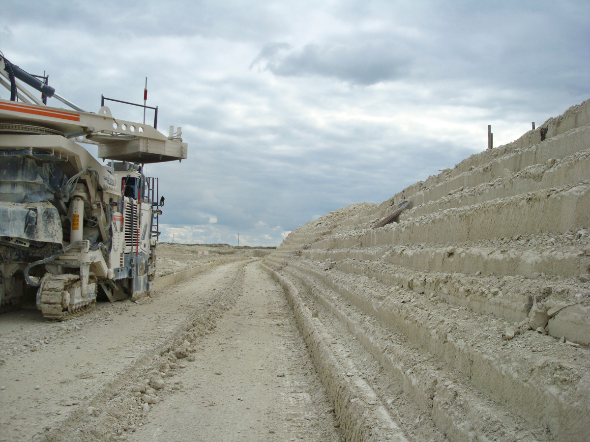
At Volsk, the operation is mining in dry conditions and the full final slope height of 85 m of chalk is exposed. Until recently, this deposit was mined by conventional drilling and blasting of 13 m benches and during the dry summer months also complemented with a surface miner (Figure 10). Since 2019, drilling and blasting has been limited to only a hard layer at the lower contact to the underlying clay, and the rest is mined directly by backhoe excavators.
A large overall slope failure was reported in the very old and abandoned pit wall in 2001. However, investigations determined the cause lay not in the initial material properties or the slope design, but in an undetected burst water pipeline at the crest of the slope.
The relatively low final overall slope angle of only 28° is a result of the operation’s permit and the large bench widths required for the electric face shovels. Similar to Obourg, the material properties would allow for steeper slopes and greater material recovery.
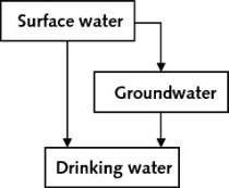
5 Impact of freezing on slope designs
It is important to note that the slope designs do not consider water pressure in the slopes. However, water from surface sources of aquifers in the overburden may seep into the chalk. This water is considered to be drained freely from the slopes. Blocking such a seepage will result in the build-up of water pressure and has to be evaluated. Blocking could be planned by grouting to reduce water inflow, or unplanned by freezing conditions. Since chalk has relatively high porosities and water contents, [6] evaluated the progress of a freezing front into chalk rock mass for cases from light (-2°C) to extreme (-30°C) freezing temperatures. Over a short time (60 minutes), the freezing front progresses 18-95 mm into the rock mass. Over a longer period (30 days), the freezing front progresses 450-2600 mm into the rock mass. Such frozen slopes may block the assumed free seepage and drainage and result in temporary water pressures. Consequently, the slope designs in a non-continu-ous mining method in drained chalk operations and harsh winter conditions should consider such pore pressure build-ups. In addition, this may also affect the selection of mining equipment.
6 Impact of non-chalk layers
Chalk often has significant flint layers. In the case of Lägerdorf, these are clearly visible and continuous but do not impact on the slope design. However, the selected mining and process equipment must be able to deal with such very hard layers within a soft chalk matrix.
The deposit at Volsk has layers for harder chalk at the contact to the underlying clays. It is suspected that this hardening is not a primary material property of the chalks, but rather a secondary cementation by groundwater flows along this boundary of lower permeability. Consequently, this part of the deposit requires drilling and blasting for excavation.
7 Conclusion
7.1 Material properties
Not all the properties are available for all three deposits, but the following conclusions can be drawn: the chalks in all three presented deposits are characterised by relatively high water contents (18-27 %) and porosities (14-44 %) and low dry densities (1.5-2.0 t/m3). Although the ranges are significant, the average of these properties are closer to each other.
The UCS is in the range of 3-14 MPa, which is considered to be ‘very weak’ (R1) to ‘weak’ (R2) according to the International Society for Rock Mechanics [4]. The tensile strength was only measured at Obourg and ranges from 0.35-1.02 MPa, which is also low.
While at Obourg there is an increase in den-sities with greater depth and a decrease of the porosity, the same could not be observed at Lägerdorf.
At Lägerdorf there was a correlation between increasing cohesion and friction angle and increasing depth. Such a correlation could not be established for Obourg due to lack of available tests.
Material strengths in Lägerdorf are severely reduced in weathered parts of the deposit, while at Volsk, potential secondary cementation resulted in an increase in the material strengths.
7.2 Slope designs
The low UCS and tensile strengths allow direct excavation without blasting damage to the slopes. Furthermore, this also allows consideration of mining methods below the water level in saturated slope conditions.
The high water contents can impact on the superficial material strength under freezing conditions. Such freezing conditions and the resulting temporary lack of drainage should be considered in the slope design approach, especially for severe temperature conditions and longer inactivity of mining faces, as well as during the selection of the mining method and mining equipment.
Weathering effects can have a severe impact on the shear strengths and this has to be considered during exploration and testing programs as well as for the resulting slope designs.
While geological structures do not seem to have a major influence on the slope designs due to the low material strengths, the shear tests at Lägerdorf suggest strong reductions of cohesions along structures and should be considered for unfavourable orientations.
The slope designs at all three operations are not optimised for maximum material recovery but are currently the result of the groundwater conditions and mining method (Obourg) or the mining permit (Volsk). There are indications that steeper final slopes are possible and these options will be pursued in the future.
Acknowledgement
The authors thank the technical management of Holcim (Belgique) SA, Holcim (Deutschland) GmbH and LafargeHolcim Russia for their support and the permission to use the presented data.