

Production and engineering application of high-volume ground limestone powder concrete
Greener and lower-carbon development has become a key priority in transportation infrastructure, increasing concerns over the resource use and carbon emissions of concrete. Concrete is one of the most widely used construction materials in highways, bridges, tunnels, and other infrastructure projects; however, its production is associated with significant carbon emissions. The production of 1 t of cement generates approximately 0.8~0.9 t of CO2 [1]. Therefore, reducing cement consumption and increasing the use of low-carbon alternatives, while maintaining the required workability, mechanical performance, and durability of concrete, is an effective way to reduce its carbon footprint.
Previous studies have quantitatively demonstrated the carbon-reduction potential of limestone powder-based cementitious materials. Kim et al. [2] reported that limestone powder replacement can reduce the CO2 emissions of concrete by approximately 8~17% depending on the replacement level. Moreover, Scrivener et al. [3,4] demonstrated that limestone-containing low-carbon cement systems (e.g., LC3) can achieve substantial CO2 reductions by reducing clinker content. These studies confirm the low-carbon potential of limestone powder as an SCM. Limestone powder is widely available and inexpensive. It can improve cementitious systems through particle filling, improved particle packing, and nucleation effects during hydration [5,6]. Its performance depends on factors such as fineness, dosage, and concrete mix proportions [7,8]. Previous studies have investigated different limestone powder replacement levels and demonstrated that an appropriate replacement level is essential for maintaining concrete performance. For example, Demirhan et al. [9] investigated limestone powder replacement levels of 0%, 15%, 25%, and 35% in self-consolidating mortars and reported that 15% replacement provided a relatively balanced performance, while higher replacement levels led to performance deterioration. Radovic´ et al. [10] evaluated reinforced concrete beams containing high-volume limestone powder concrete under sustained loading for 1000 days and reported reduced shrinkage, creep, crack width, and long-term deflection compared with ordinary concrete. Shrinkage-induced cracking is a critical durability concern for concrete incorporating high volumes of mineral admixtures, particularly in highly restrained infrastructure such as highway bridges and culverts. Khatib et al. [11] reported that the incorporation of limestone fines increased the drying shrinkage of mortar with increasing replacement level, while low replacement levels of up to 10% also promoted chemical and autogenous shrinkage. In contrast, Li et al. [5] found that increasing the limestone powder content in UHPC reduced autogenous shrinkage but increased drying shrinkage, leading to a non-monotonic change in total free shrinkage.
However, existing investigations have mainly focused on commercially produced limestone powder under laboratory conditions, while the production of limestone powder from stone processing tailings and its application at relatively high replacement levels in large-scale engineering projects remain insufficiently studied. Further research is therefore needed to determine an appropriate replacement level and to verify whether consistent performance can be achieved across different strength grades under practical engineering conditions.
Professor Yang Wei’s research team at Nanjing Forestry University developed key technologies for concrete with a high content of finely ground limestone powder and applied them in an expressway project in Guilin, Guangxi. The project has a total route length of 18.3 km and requires approximately 700,000 m3 of concrete. The project area features typical karst landforms, and most of the excavated rock is limestone, with a total volume of approximately 2.72 million m3. An aggregate processing plant was established on site to process the excavated rock into concrete aggregates. The plant is expected to produce about 1.3 million t of aggregates, along with approximately 65,000 t of stone powder tailings. To improve the utilization of this by-product, the tailings are further ground into limestone powder and used as a supplementary cementitious material to replace a substantial proportion of cement. Compared with previous studies mainly focusing on commercially produced limestone powder, this study establishes an integrated approach involving the on-site production of limestone powder from stone powder tailings, concrete mix optimization, and engineering application. Based on the actual demand for C20~C40 concrete, the performance of the developed limestone powder concrete was evaluated and verified through field application.
2.1 Collection of stone powder tailings
The aggregate processing plant (Figure 1) was located to minimize the transport distance for both quarried limestone and finished aggregates. It is approximately 500 m from the limestone source and covers an area of approximately 21,750 m2. The concrete mixing plant, cement-stabilized soil mixing station, and asphalt mixing plant are all located adjacent to the aggregate processing plant. After processing and quality inspection, aggregates of different sizes are conveyed directly to the storage bins at the mixing plants, minimizing secondary handling on site.
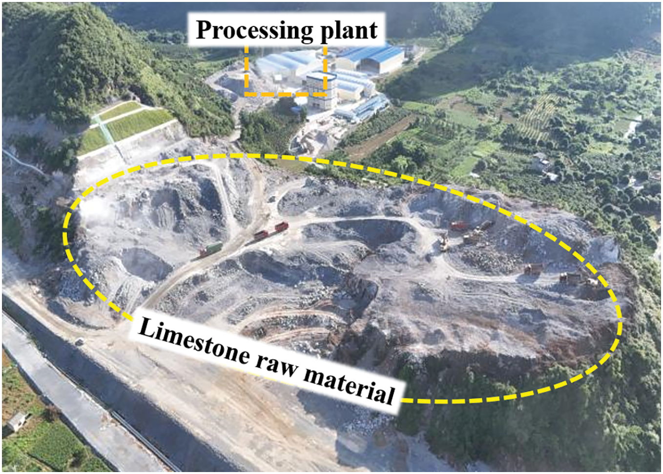
Figure 1 Limestone quarry and aggregate processing plant
The aggregate production process consists of four main stages:
(i) Primary crushing. Oversized limestone blocks are first reduced to less than 600 mm using a hydraulic breaker. After selection by an excavator, the material is fed into a ZSW110 × 490 grizzly feeder. Clay lumps and debris smaller than 50 mm are conveyed by belt to a vibrating screen for separation, which serves as the first stage of clay removal. The remaining rock is fed into a PE750 × 1060 jaw crusher for primary crushing.
(ii) Secondary cone crushing. The primary-crushed material is conveyed by a B1000 belt conveyor to an STC1400 cone crusher for secondary crushing. The crushed material is then classified by a 2YK2670 vibrating screen. The 0~4.75 mm fraction undergoes a second clay-removal step, while particles larger than 40 mm are returned to the cone crusher for further crushing.
(iii) Particle shaping. After cone crushing, the material is conveyed to a surge bin and then fed by a GZD1225 feeder onto a belt conveyor. It is subsequently delivered to a VSI1145 vertical shaft impact crusher for particle shaping and manufactured sand production (Figure 2a). After primary crushing, cone crushing, and shaping, the finished aggregate has a well-formed particle shape, with a combined content of flaky and elongated particles of only 1.5%.
(iv) Screening and fines classification. The shaped material is classified by vibrating screens. Aggregate fractions of 16~31.5 mm, 10~20 mm, and 5~10 mm are conveyed separately to the finished-product stockpiles. The 0~4.75 mm sand fraction enters the fines classification system, where the fines content is controlled below 10% by adjusting the classifier power. After quality inspection, aggregates of different sizes are conveyed directly to the storage bins of the adjacent mixing plants. The 10~20 mm coarse aggregate produced from limestone through crushing, screening, and shaping was used as the raw material for finely ground limestone powder. The coarse aggregate was required to meet the following specifications: crushing value ≤20%, combined content of flaky and elongated particles ≤10%, clay content ≤1%, clay lump content ≤0.2%, apparent density ≥2600 kg/m3, and compressive strength of the parent rock ≥80 MPa (Figure 2b).
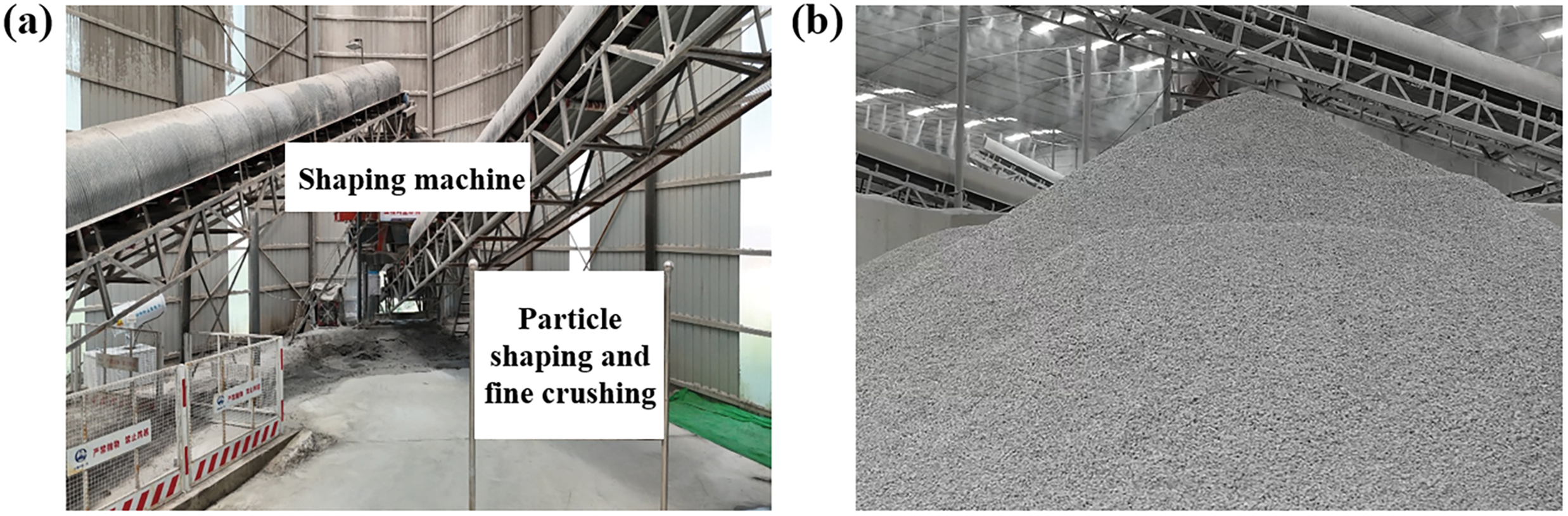
Figure 2 Aggregate shaping machine (a) and finished coarse aggregate (b)
2.2 Preparation of finely ground limestone powder
The production process for finely ground limestone powder is shown in Figure 3. Stone powder tailings generated by the vortex classifier during aggregate processing (Figure 4) were used as the raw material. The tailings contained at least 75% CaCO3 and no more than 1% moisture [12]. After pretreatment, the 70-mesh stone powder tailings were mixed with 10~20 mm crushed limestone at a mass ratio of 1:1 and continuously fed into a Raymond grinding system through a metering feeder. Inside the Raymond mill, the grinding rollers revolve around the central axis and are pressed against the stationary grinding ring under centrifugal force. The material is crushed and ground between the grinding rollers and the grinding ring. Grinding the tailings together with coarser limestone particles improves the particle-size distribution and helps reduce the agglomeration and adhesion of fine particles. After grinding, the particles are carried by airflow from a high-pressure centrifugal fan to a high-efficiency turbine classifier. Fine particles meeting the target size are transported to a cyclone separator for gas-solid separation and collected as the finished limestone powder. Coarser particles are returned to the grinding chamber for further grinding, forming a closed-circuit grinding process. Powder fineness and particle-size distribution are controlled by adjusting the classifier speed, airflow rate, and air pressure. To ensure consistent powder properties, the classified powder is further screened and then collected separately or blended in specified proportions according to the test requirements. This allows effective control of powder fineness and particle-size distribution. The Raymond grinding system used in the project is shown in Figure 5.
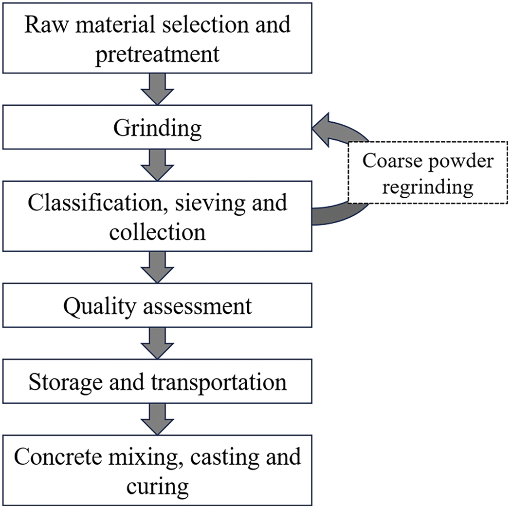
Figure 3 Preparation process for finely ground limestone powder
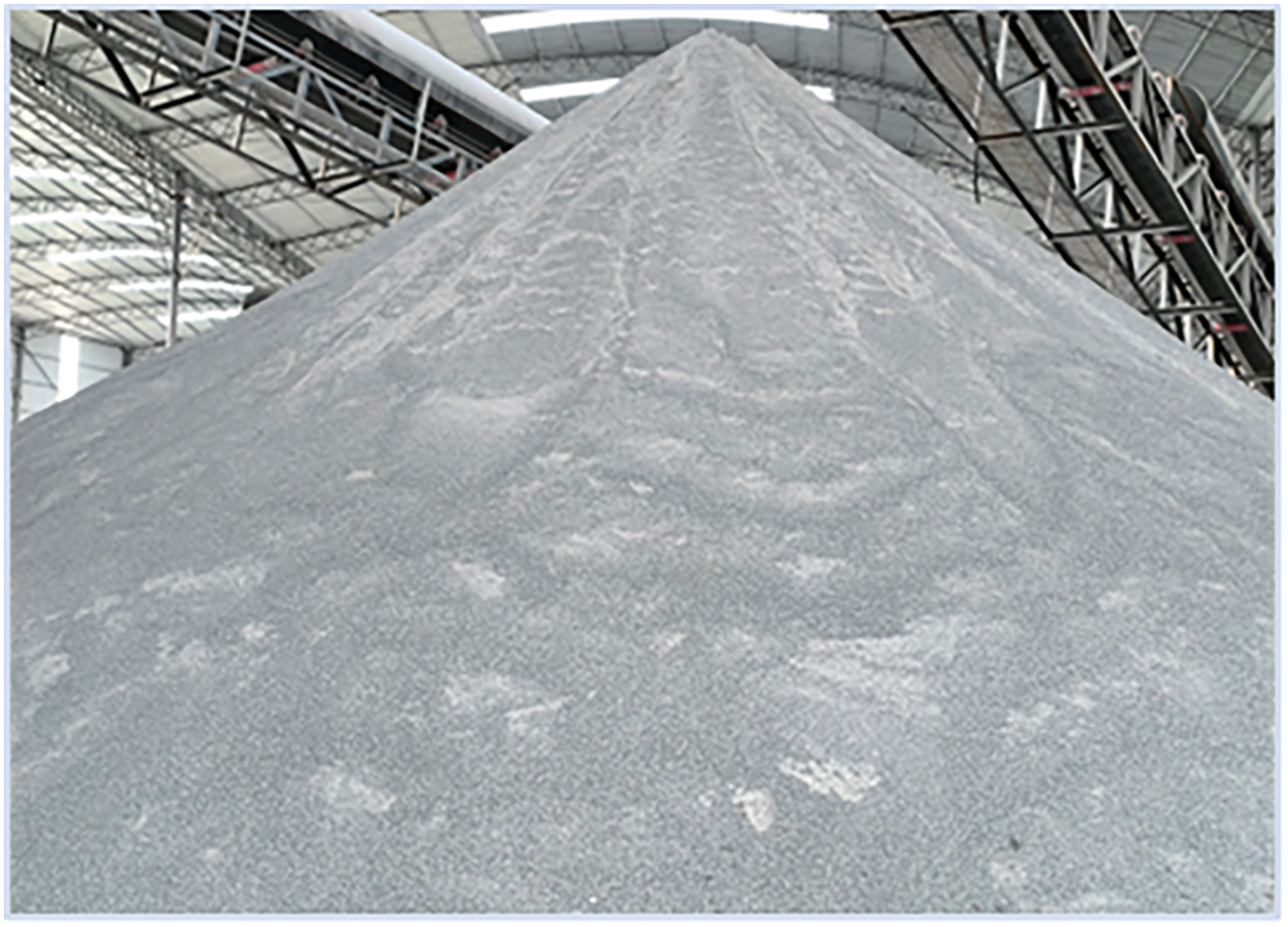
Figure 4 Stone powder tailings from manufactured sand production
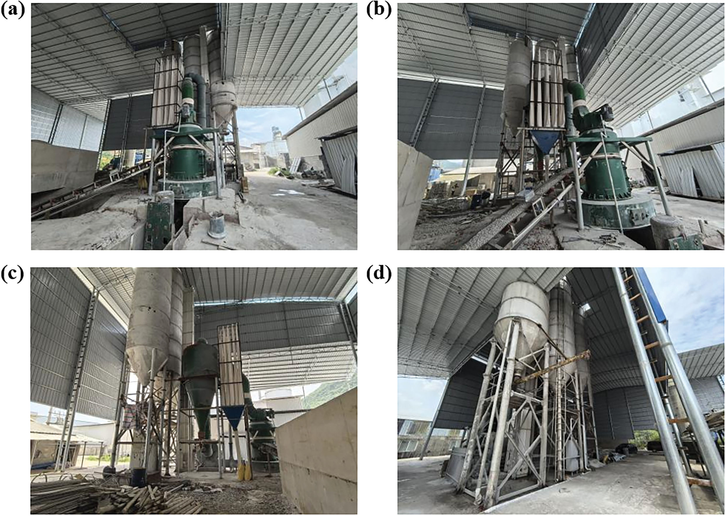
Figure 5 Production equipment: Raymond mill (a), classifier (b), cyclone separator (c), and finished-product storage tank (d)
The properties of the limestone powder are summarized in Table 1. The powder is grayish white, with a uniform appearance and no visible impurities. The morphology and particle size distribution of the 400-mesh sample were analyzed using scanning electron microscopy (SEM) and a Mastersizer 2000 laser particle size analyzer. A photograph of the powder, the SEM image, and the particle size distribution are shown in Figure 6.

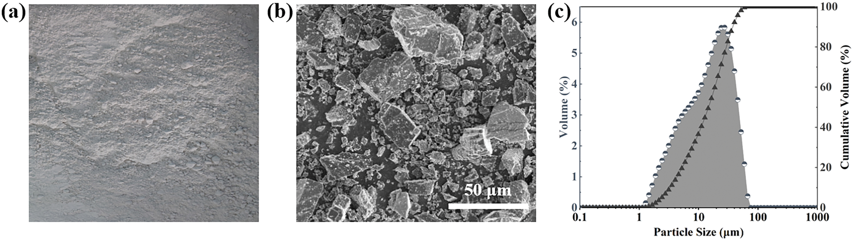
Figure 6 Characterization of limestone powder: photograph (a), SEM image (b), and particle size distribution (c)
3 Mix design and performance characterization of limestone powder concrete
3.1 Optimization of concrete mix proportions
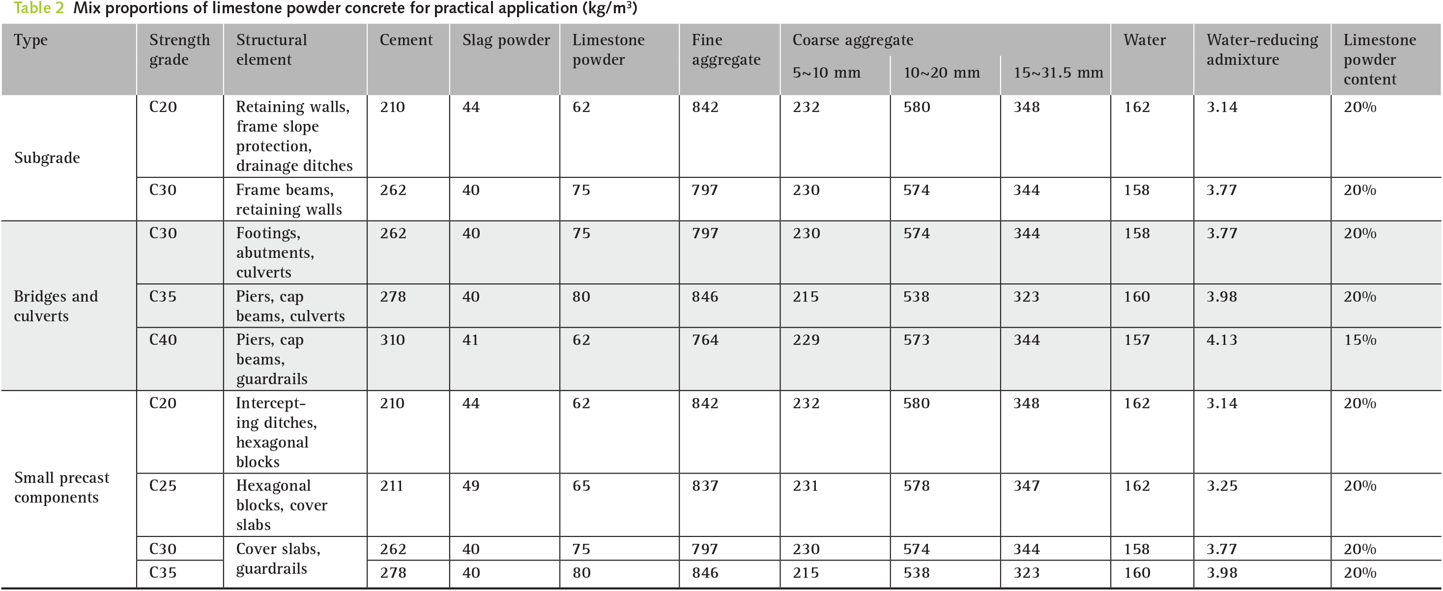
A Box-Behnken response surface design was used to evaluate the effects of four factors on the workability and mechanical properties of limestone powder concrete: limestone powder content, slag powder content, water-to-binder ratio, and limestone powder fineness. Each factor was investigated at three levels, giving a total of 29 mix designs. Compressive strength was measured at 3, 7, and 28 days. Response surface models were then established to assess the significance of the individual factors and their interactions. The results showed that the effect of limestone powder content on compressive strength was influenced by the water-to-binder ratio and limestone powder fineness, with a clear interaction between content and fineness. Response surface methodology was then used to optimize limestone powder content, slag powder content, water-to-binder ratio, and fineness. The predicted results were further adjusted for different concrete strength grades, structural applications, service requirements, on-site materials, and production conditions, leading to the final mix proportions shown in Table 2.
3.2 Mechanical properties and hydration characteristics of limestone powder concrete
Limestone powder replaced ordinary Portland cement at 10%, 15%, 20%, and 25%, and compressive strength, stress-strain behavior, and heat of hydration were tested to determine a suitable replacement range. As shown in Figure 7, the stress-strain behavior was similar to that of conventional concrete, with predominantly brittle failure. Strength and elastic modulus generally decreased with increasing limestone powder content. At replacement levels of 15%~20%, the decreases were slight, whereas mechanical properties declined more noticeably at 25%.
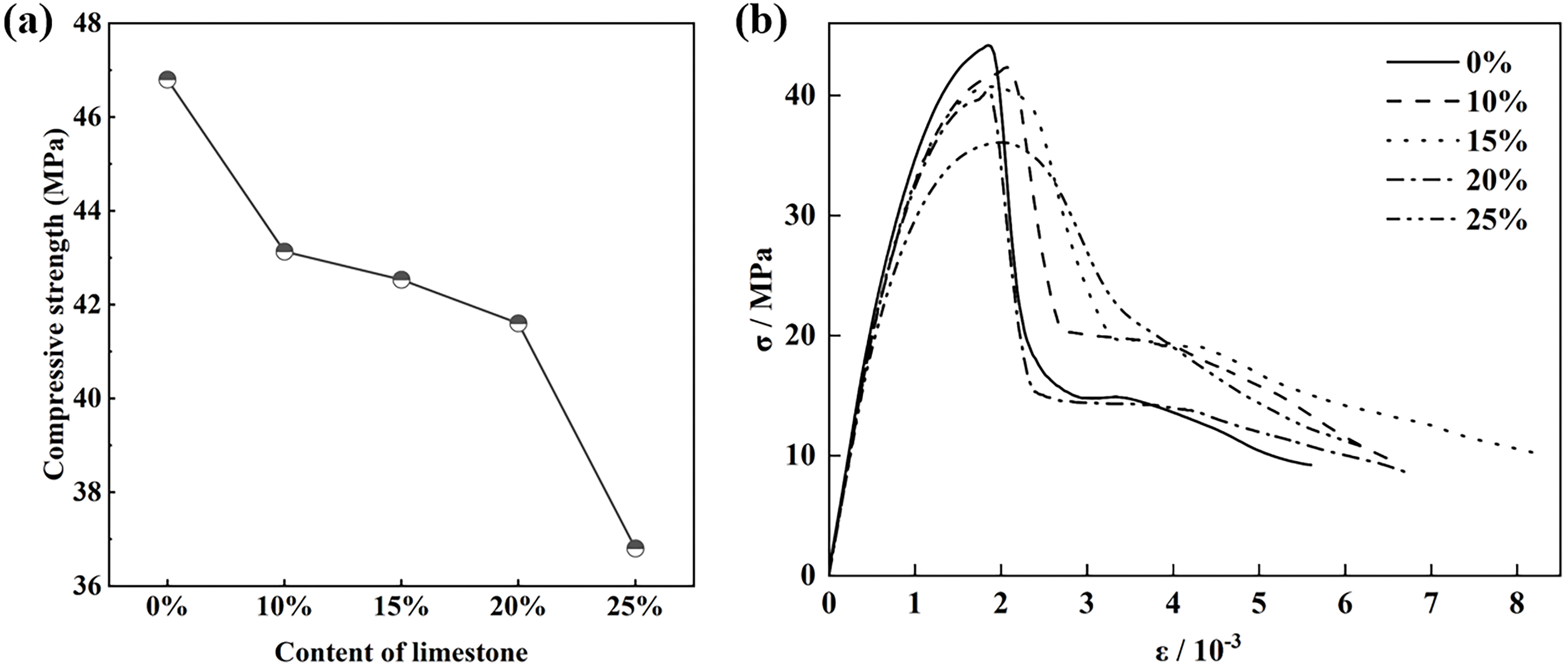
Figure 7 Compressive strength (a) and stress-strain curves (b) of concrete with different limestone powder contents
As shown in Figure 8, increasing the limestone powder content shortened the induction period and shifted the main hydration peak to an earlier age, indicating an acceleration of early cement hydration. The main hydration peak occurred at approximately 19.6, 18.5, 17.7, 17.0, and 16.6 h for the mixtures containing 0%, 10%, 15%, 20%, and 25% limestone powder, respectively. The earlier hydration observed in this study is consistent with Berodier and Scrivener [13], who showed by isothermal calorimetry and SEM that limestone accelerates clinker hydration through reduced interparticle spacing and enhanced C-S-H nucleation. In addition to the calorimetric evidence, Lothenbach et al. [14] provided complementary microstructural evidence from XRD and TGA, showing that limestone can modify the hydrate assemblage by promoting monocarboaluminate formation and stabilizing ettringite. These findings further support the role of limestone in modifying cement hydration beyond its physical filler effect. However, at higher limestone powder replacement levels, the cumulative heat release decreased because the reduction in reactive clinker gradually outweighed the hydration-acceleration effect of limestone. Consequently, the dilution effect became increasingly dominant, which was consistent with the observed reduction in mechanical performance. Considering mechanical performance, hydration behavior, and resource utilization, a replacement level of 15%~20% was selected for engineering application.
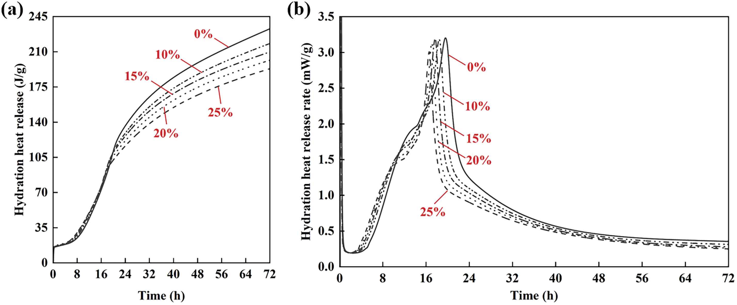
Figure 8 Cumulative heat release (a) and heat release rate (b) of cementitious systems with different limestone powder contents
4 Engineering application and evaluation
To evaluate the practical applicability of concrete containing finely ground limestone powder, large-scale applications were carried out in subgrade works, bridges and culverts, and small precast components, followed by on-site monitoring. The main parameters included compressive strength, rebound strength, carbonation depth, and concrete whiteness. For carbonation measurement, multiple points were selected at each monitored location, and the average carbonation depth was calculated for each location. The maximum value among the average carbonation depths of all monitored locations was reported as the maximum average carbonation depth. Strength and carbonation were monitored at 7, 28, 56, and 180 days, while whiteness was measured with a colorimeter at 28 days after casting.
The project includes 12 subgrade sections with a total length of 10.649 km and approximately 159,000 m3 of concrete. Field measurements of carbonation depth, compressive strength, and rebound strength were conducted at different locations and structural elements. At 28 days, the maximum average carbonation depth was 0.7 mm, while compressive and rebound strengths reached at least 126% and 115% of the design values, respectively. At 180 days, the maximum average carbonation depth was 5.2 mm, and the corresponding strengths reached at least 141% and 143% of the design values. In addition to meeting the design and specification requirements, field measurements of whiteness showed that finely ground limestone powder noticeably improved the appearance of exposed concrete. The application is shown in Figure 9.
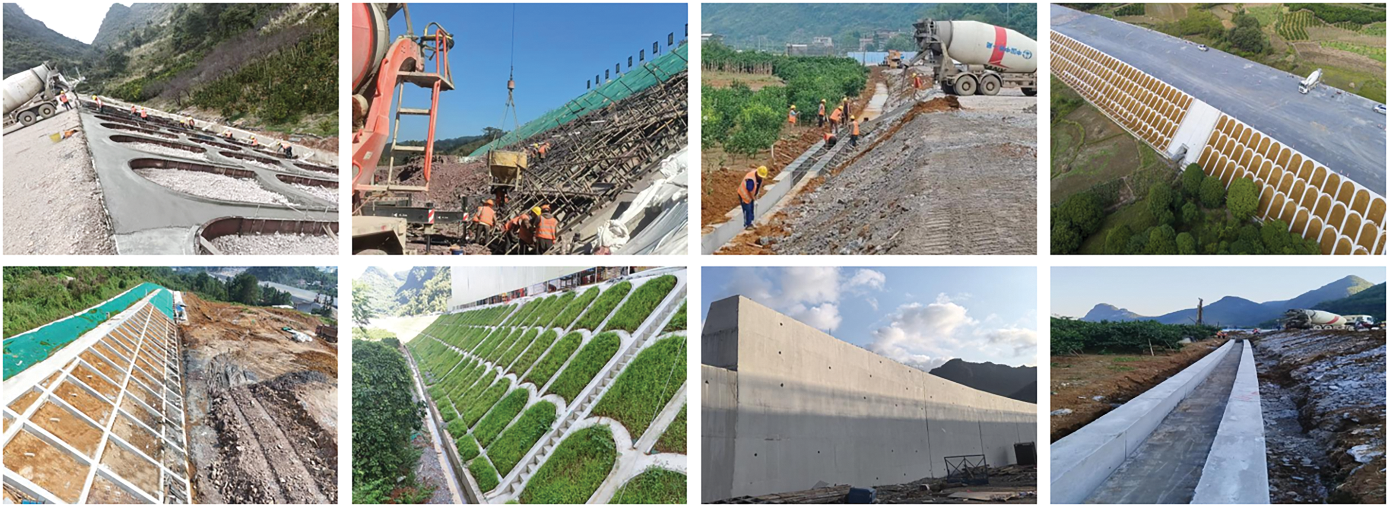
Figure 9 Production and application of limestone powder concrete in subgrade works
The project includes 6 mainline bridges and 6 ramp bridges, with 955 piles, 857 piers, 346 cap beams, 27 abutments, and 34 culverts totaling 1616 m. The total concrete volume is approximately 191,000 m3. Long-term monitoring showed that the maximum average carbonation depth was 0.7 mm at 28 days, while compressive strength and rebound strength reached at least 101% and 95% of the design values, respectively. At 180 days, the maximum average carbonation depth was 4.6 mm, and the corresponding strengths reached at least 132% and 133% of the design values. All measured parameters met the design and specification requirements. The application is shown in Figure 10.
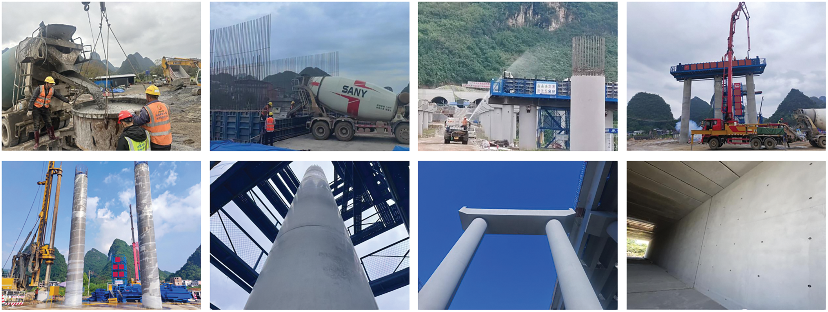
Figure 10 Production and application of limestone powder concrete in bridge and culvert works
Finely ground limestone powder concrete was also used in precast components, including hexagonal blocks, drainage ditch covers, manhole covers, lateral blind-drain covers, culvert covers, and concrete barriers, with a total design concrete volume of approximately 19,000 m3. At 28 days, the maximum average carbonation depth was 0.8 mm, while compressive strength and rebound strength reached at least 103% and 98% of the design values, respectively. At 180 days, the maximum average carbonation depth was 5.0 mm, and the corresponding strengths reached at least 143% and 137% of the design values. Components of all strength grades met the design and specification requirements. The application is shown in Figure 11.
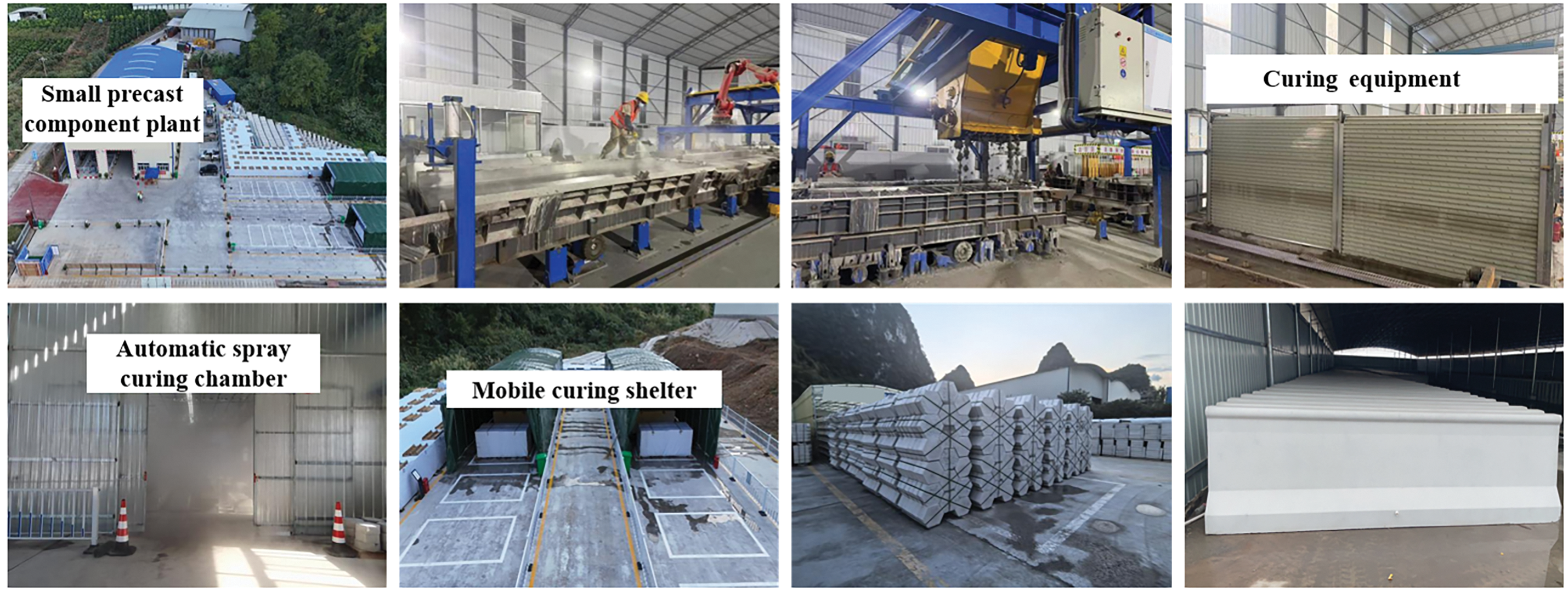
Figure 11 Production and application of limestone powder concrete in small precast components
5 Summary of application outcomes
The project involves 6.54 million m3 of earthwork engineering, including 2.72 million m3 of rock excavation, and approximately 1.30 million t of aggregates. To improve resource utilization and reduce solid waste, stone powder tailings and crushed limestone were ground at a 1:1 mass ratio to produce finely ground limestone powder, which replaced 15%~20% of cement. By optimizing the concrete mix proportions and construction process, the material was successfully used in C20~C40 concrete. It has been applied in subgrade works, bridges and culverts, and small precast components, establishing a practical approach for recycling stone powder tailings and producing limestone powder concrete.
Engineering application showed that approximately 42,800 t of finely ground limestone powder was used. Its incorporation reduced cement consumption while maintaining the required concrete performance, with the measured strength and carbonation depth satisfying the design and specification requirements. Its light color also helped reduce visible surface defects and improve the overall appearance. The estimated economic benefit was approximately RMB 16.581 million, including cost savings from replacing externally purchased limestone powder with on-site produced material (RMB 1.636 million), reduced waste disposal and land restoration costs (RMB 0.152 million), and lower binder material costs resulting from limestone powder incorporation (RMB 14.793 million). The technology also reduced solid-waste stockpiling, transportation, and land occupation, while lowering cement consumption and construction costs, demonstrating combined economic and environmental benefits.
Overall, stone powder tailings from aggregate processing can be effectively used as a concrete mineral admixture after proper processing and quality control. Even at relatively high cement replacement levels, the concrete can still meet engineering performance requirements. For wider application, attention should be given to variations in stone powder quality and dosage from different sources. Reliable concrete performance and construction quality can be maintained through strict raw material testing and processing control, optimized mix design, and field verification. For long-term engineering applications, further investigation incorporating shrinkage-related properties and cracking resistance would help extend the present findings and provide a more comprehensive assessment of high-volume limestone powder concrete under different structural restraint and environmental conditions. With increasing demand for green and low-carbon construction, finely ground limestone powder has strong potential for broader engineering applications.
Acknowledgement
Not applicable.
Funding Statement
This study was supported by the National Natural Science Foundation of China (No. 52378244), Postgraduate Research & Practice Innovation Program of Jiangsu Province (26CXJH2184), and the Science and Technology Research and Development Program of China Railway Group Limited (Grant No. Practical 2023-Key-19).
Author Contributions
Conceptualization, Hang Yang, Yang Wei and Pan Sun; methodology, Binrong Zhu; validation, Pan Sun, Ke Meng and Jinlong Wang; formal analysis, Xiaokang Qian; investigation, Binrong Zhu and Xiaokang Qian; resources, Pan Sun and Ke Meng; writing—original draft preparation, Hang Yang, Binrong Zhu and Xiaokang Qian; writing—review and editing, Hang Yang, Yang Wei, Binrong Zhu, Pan Sun, Ke Meng, Jinlong Wang and Xiaokang Qian; funding acquisition, Yang Wei. All authors reviewed and approved the final version of the manuscript.
Availability of Data and Materials
Data are contained within the article.
Ethics Approval
Not applicable.
Conflicts of Interest
Authors Pan Sun, Ke Meng and Jinlong Wang were employed by the company China Railway First Group First Construction Co., Ltd. The authors declare no other conflicts of interest.