Belt cleaners on high volume raw material conveyors
 Martin Engineering 2025
 Martin Engineering 2025
 Martin Engineering 2025
 Martin Engineering 2025
 Martin Engineering 2025
 Martin Engineering 2025
CEMA recommendations on placement and positioning
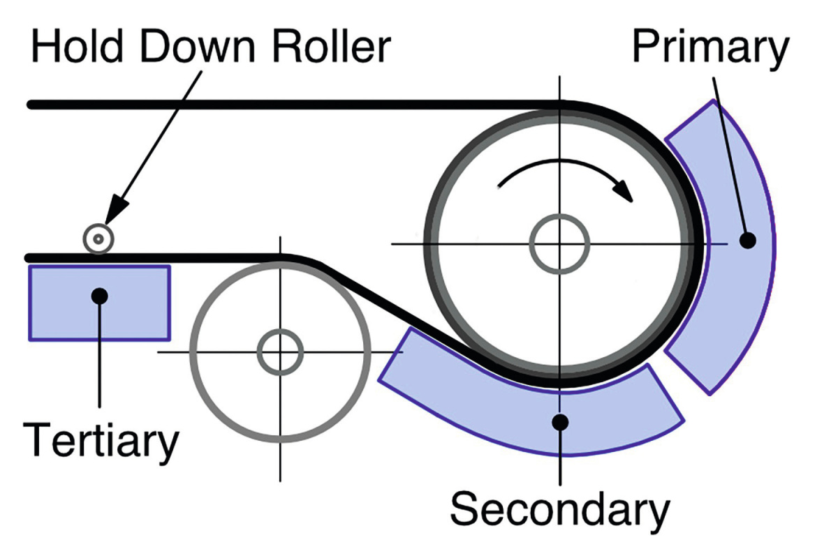
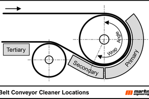
The Conveyor Equipment Manufacturers Association (CEMA) defines the secondary position as the space between the head pulley and the snub pulley on the return run of the belt. (Figure 2) Unfortunately, structural designs often result in a very short section of belt surface between the head pulley and the snub pulley, which is the ideal location for many secondary cleaner designs. This limited distance leaves little room for belt cleaners in the secondary position, which is further complicated by the space needed for a dribble chute. Additionally, designers often place work platforms based on major components, overlooking access for belt cleaner inspection or maintenance. Belt cleaners typically require more attention than major components to ensure system efficiency because the blades are wear components that must be maintained at optimal cleaning pressures.
Design and installation considerations
There are many simple options designers should consider:
1. Is the drive pulley wrap angle really needed or are you just applying it from habit? A common default wrap is 210 degrees, created by the position of the snub pulley. The gap between the head pulley and snub pulley is an ideal location for a secondary cleaner, but the combination of pulley diameters and wrap angle may make mounting a secondary cleaner difficult and maintenance nearly impossible. We recommend utilizing an updated engineering design program that uses either the DIN or CEMA methods for calculating accurate tension values and the required wrap angle, θ
2. Consider using a larger diameter head pulley. Choosing a head pulley based on the minimum diameter may seem like it saves money, however, MSHA reports that up to 85% of maintenance problems are due to fugitive materials, which increase costs for cleanup, labor, and equipment replacement.[1] A larger head pulley can allow the installation of two cleaners in the primary position and enough snub pulley space for one or two cleaners in the secondary position, significantly reducing the amount of fugitive material. (Figure 3)
3. Place a priority on ergonomic access to the belt cleaners. Maintenance personnel can spend up to a third of their time simply gaining access to equipment. Designing access to seldom-inspected or -maintained components based on minimum walkway codes increases costs. Consider structures and work platforms that facilitate belt cleaner inspection and maintenance
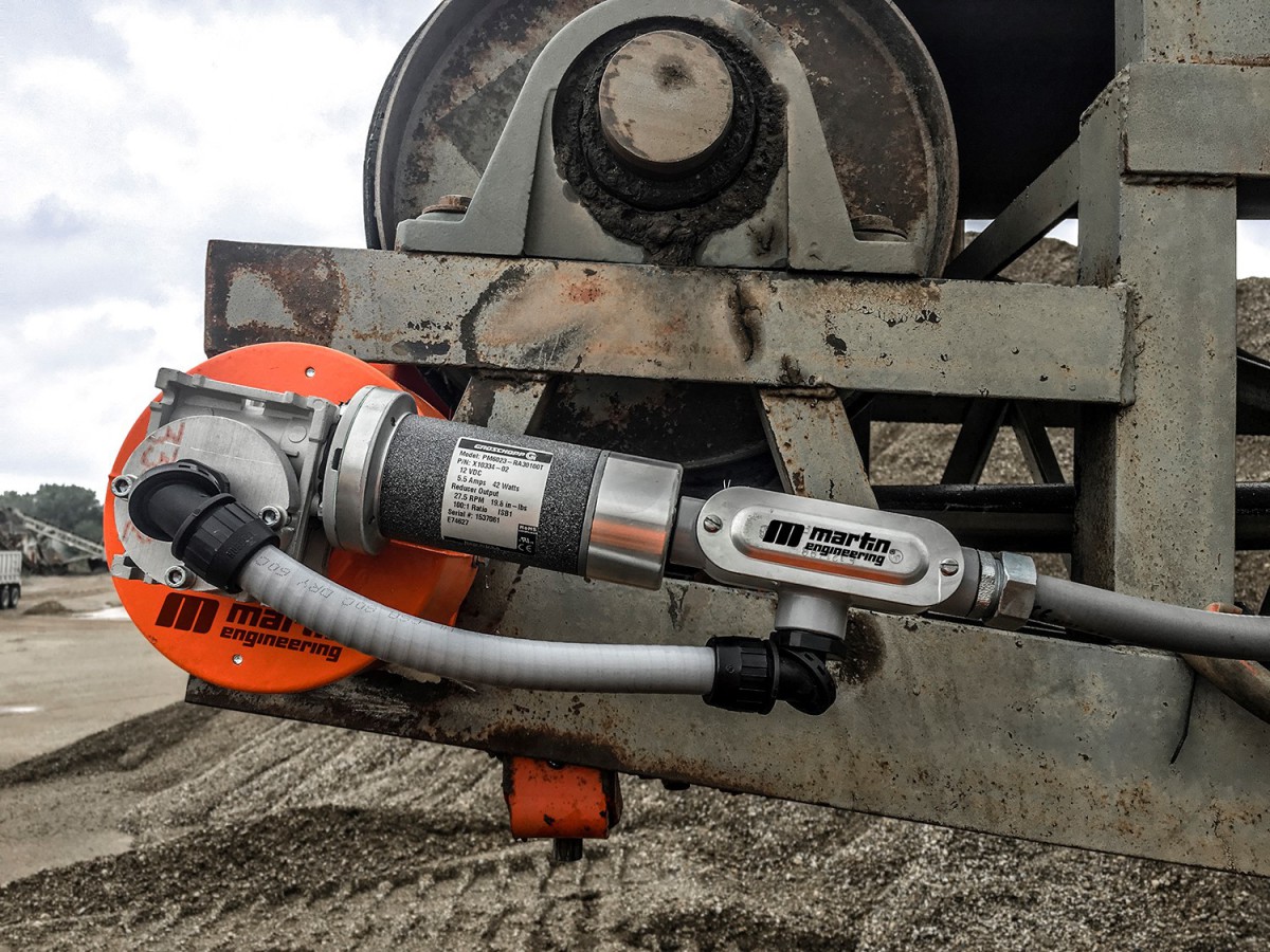
4. Consider using motorized drive pulleys. Motorized pulleys offer energy advantages and weight savings and open up space for belt cleaner installation and maintenance. Since all rotating components (including the main bearings) are located inside the pulley, the external stub shafts need minimal space to be mounted to the structure
5. Consider professionally trained installation. Belt cleaners must be mounted accurately, typically within a few millimeters, to operate optimally and reduce the risk of damaging the belt. Partnering with the belt cleaner supplier guarantees proper installation with minimal adjustments and ensures that the new chute maintains a clean, professional appearance
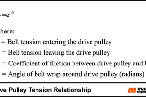
Calculating the adequate belt tension
A critical design requirement is to determine the amount of wrap around the drive pulley necessary to ensure adequate torque conversion from the drive into belt tension sufficient to move the belt without slipping. It is interesting to note that the fundamental relationship describing this transfer does not depend on the pulley diameter, but rather on the coefficient of friction, µ, between the belt and pulley, the wrap angle, ϴ, and the belt tensions required to prevent slip. (Figure 4)
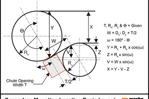
Secondary belt cleaner location geometry
Assumption: Top and bottom runs of the conveyor belt (X) are parallel entering head pulley and leaving snub pulley. (Figure 5)
Variables:
θ = Wrap angle of belt around head pulley.
ω = Wrap Angle, θ, - 180 degrees.
H = The height of the opening for the Secondary belt cleaner blades and frame installation.
Rh = Radius of Head pulley plus lagging, plus belt thickness
Rs = Radius of Snub pulley plus lagging, plus belt thickness. (Snub Pulley Diameter default value: 0.64 × head pulley diameter per DIN 22101)
T = The width off the opening for the Secondary belt cleaner blades and frame installation.
W = Length of belt segment tangent to both the Head and Snub pulleys.
X = Distance between top and bottom runs of the conveyor belt.
Y = The vertical distance between the top run of the conveyor belt on the Head pulley and the tangent point where the belt leaves the Head pulley and starts the return run.
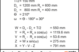
Some secondary cleaners must be installed at least 50 mm from the point where the belt leaves the head pulley, so this offset should also be considered if needed. Additionally, the X dimension must be verified against the idler dimensions to ensure sufficient installation space. (Figure 6)
A similar analysis of the placement of precleaners indicates that with a 1200 mm diameter head pulley, two primary cleaners can be installed alongside a secondary cleaner. The inclusion of tertiary cleaners is possible, but may not be necessary if two precleaners and a secondary are mounted on the head pulley.
Conclusion
A belt cleaner system should be properly specified, designed and installed to gain the direct and indirect long-term cost benefits of reduced fugitive material, but compliance is an issue as well. OSHA, 1926.1412(d)(1) and MSHA 75.362 state, “A competent person must begin a visual inspection prior to each shift the equipment will be used, which must be completed before or during that shift.” [2] Safe access with adequate space for installation, maintenance and inspection is critical to supporting longer system life and a lower cost of operation.