Mixing technology for conditioning of recovered fuels
 Eirich
 Eirich
 Eirich
 Eirich APS
 Eirich APS
 Eirich APS
 Eirich APS
 Eirich
 Eirich
 Eirich
 P. Holthaus, University of Siegen
 P. Holthaus, University of Siegen
 P. Holthaus, University of Siegen
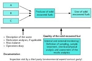
The production of Solid Recovered Fuels (SRF) often involves many different mixing tasks. Two main mixing systems are available here. This article compares the properties of both systems and provides examples of applications to highlight when each system is beneficial for a particular application.
1 Introduction
The use of recovered fuels is an important element in cost-effective and low-emission energy supply. The production of high-quality recovered fuels requires suitable mixing plants in which a wide range of different waste materials can be processed and conditioned in the best possible way. In this article we present several units that are suitable for this.
2 Substitute fuels – terms, demand, consumers and requirements
2.1 The term recovered fuels
The term ‘Solid Recovered Fuel’ (SRF) is used to describe waste derived fuels that are used to replace fossil fuels previously used in thermal processes. Solid Recovered Fuels (or just ‘recovered fuels’ for short) are also referred to as secondary fuels and are a subgroup of alternative fuels or Refuse Derived Fuels (RDF), which also include biogenic fuels such as bioalcohols, hydrogen, and fuels from gasification or fermentation processes.
2.2 Growing demand
Demand is steadily growing for recovered fuels produced from commercial, household, and special waste. This is because industrial consumers can benefit financially from substituting them for primary energy carriers (mostly gaseous, liquid, or solid fossil fuels) – in some cases, suppliers will even pay them to take recovered fuels off their hands. Recovered fuels also ease pressures on landfill sites by reducing the amount of waste that needs to be deposited. Co-incineration of waste together with fossil fuels costs less than disposal via special waste incineration plants. The reduction in levels of CO2 emissions that have to be accounted for when primary fuels are used is very significant in terms of environmental policy.
2.3 Users of recovered fuels
Industrial furnaces where co-incineration of recovered fuels may be of interest include e.g. cement and lime works as well as power stations that use hard coal or lignite. In terms of heat output, the contribution of recovered fuels is usually below 25%. One exception to this are cement plants, where recovered fuels already make up the bulk of the heat carriers that are used as fuel today in Germany; materials used include e.g. used tires, waste oil, solvents, animal meal, animal fats and paper sludge/paper pulp residue produced during waste paper recycling. In recent decades, power stations have also been built that solely use recovered fuels as their source of energy for electricity and heat generation.
In the cement industry, it is advantageous that the recovered fuels can already be added in the rotary kiln infeed. This makes it possible to use vehicle tires without chopping them up first, which then combust on the way to the rotary kiln outfeed. The calorific value of used tires is equivalent to that of hard coal, and the steel reinforcement of the tires is used as a source of iron in clinker production.
2.4 Reprocessing of waste materials
SRF is usually only produced from waste that can no longer be recycled but also has a relatively high calorific value. Before these materials can be reused in existing furnaces – such as in grate firing, fluidized-bed combustion, or rotary kiln combustion – the waste materials need to be reprocessed and conditioned accordingly. The waste to be processed can have a liquid, paste-like, set, or solid consistency. For industrial consumers, it may be important to ensure that the energy content/calorific value is kept as consistent as possible so that thermal processes can be carefully controlled. For this reason, different types of waste are often mixed together. Of course, this is very straightforward if the materials are liquid; in addition, provided the flash point is sufficiently high they can be easily stored, transported, filled into tank systems, and conveyed to the furnace in the thermal plant without further conditioning and with no need for complicated safety technology.
With waste materials that are solid or paste-like, it is important to control parameters like moisture levels, chlorine content, and heavy metals content. The waste products are fed to a crusher or shredder and then on to a mixing process, where they are mixed with aggregates like sawdust, kieselguhr, or powdered waste to ensure that the mix offers consistently good properties in terms of its ability to be conveyed and dosed. In this way, commercial waste and industrial waste – for example from the paints and coatings industry, from plastics processing, and from the pulp industry – are reused as a source of energy in thermal processes, as are non-recyclable packaging remains, sewage sludge, and the calorific components of household and municipal waste.
2.5 Requirements for recovered fuels
For many applications, the only important factors are the calorific value and the physical properties required by the fuel user. However, there are also applications that require a certain chemical composition; for example, the composition of the ash plays an important role for uses in the cement industry, where it needs to reflect the chemistry of the raw cement material mix, with calcium and silicon compounds.
3 Production of recovered fuels
3.1 Homogenization and conditioning with mixers
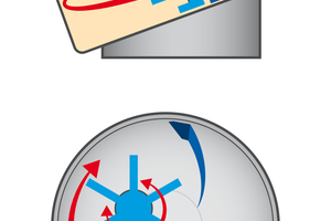
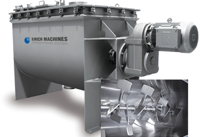
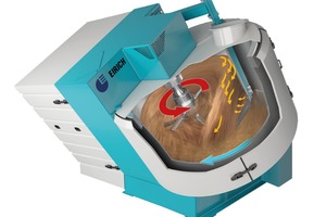
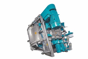
There are a number of companies in the market who take waste and process it into liquid or solid SRF with defined properties. Among other things, mixing plants are used to homogenize and condition the mix. For example, liquid or paste-like substances can be mixed with sawdust into SRF. Waste materials (such as the shredder light fraction from end-of-life vehicles and the plastic fraction from shredded household and electronics equipment or flammable domestic waste materials) are often homogenized in large drums, after which they are blended with flammable liquids/mixed to form SRF. Horizontal mixers (schematic drawing, Figure 1) and compulsory mixers with a rotating mixing pan and an eccentrically arranged mixing tool, which are known as Eirich mixers (Figure 2), can be used here, i.e. compulsory mixers that operate as throwing mixers. In many cases the mixing process needs to take place underneath a shield of inert gas. This requires “leak-tight” mixing units, as is the case with horizontal mixers and Eirich mixers.
In the following we will take a closer look at these mixing systems suitable for SRF preparation and conditioning.
3.2 Mixing system – horizontal mixer
Horizontal mixers are often referred to as plowshare mixers. These mixers are comparatively easy to manufacture. Accordingly, there are many suppliers; there are hundreds of them worldwide.
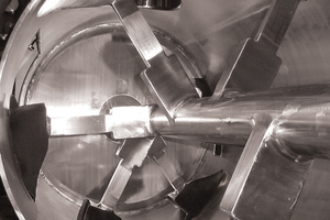
In a horizontal mixer, the material being mixed is moved by means of mixing tools that have a shape similar to a plowshare or paddle, and these tools run close to the wall (Figure 3). They pick up the material being mixed from the wall and, depending on the rotational speed, move it in the mixing container in a circulating motion in a fixed bed (Froude number below 1) or in a mechanically generated fluidized bed. In this operating status as a throwing mixer, the mixers run with a Froude number between 1 and 7; higher Froude numbers produce the operating state of a ring layer mixer [1]. The dimensionless Froude number Fr describes the ratio of centrifugal forces to gravity; strictly speaking, it only applies if the mixing tool axis is horizontal.
The mixing tools of the horizontal mixer thus run within a limited speed range. They are not capable of solubilizing agglomerated mixtures.
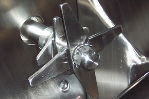
For this reason, additional choppers are used (Figure 4). These rotate at a speed of 1500 or 3000 rpm and generate high localized shear forces within a small volume directly around the choppers.
In this way it is possible to achieve much better solubilization performance, e.g. for agglomerated substances. The choppers are positioned between the travel paths of the mixing blades, so there are no mixing tools in places where the choppers are located. In granulating and drying processes the use of choppers can generate a fine fraction and therefore unwanted dust.
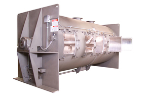
Horizontal mixers are available in a range of different types, with the mixing container having either a tubular shape (Figure 5) or running into a box shape at the top (Figure 6). They are used today in many industries. The food and pharmaceuticals sectors in particular cannot be imagined without these mixers. Eirich also produces these mixers in the USA for these applications under the product series APS (American Process Systems).
The speed of the tools in the horizontal mixer depends on the material being mixed, the size of the mixer, and the filling capacity. Naturally, the number of paddles on the shaft increases if the mixing container is longer. The mixing time is also longer then. One manufacturer explained this as follows: “This causes a growing distance when transporting each particle from fully left to fully right. This axial transport is the time-determining part of mixing performance” [2].
Due to this problem of slow axial transport on horizontal mixers, the material needs to be added in the middle to prevent mixing times from becoming unnecessarily long. Liquids generally need to be injected through nozzles into the mixing chamber. One manufacturer states that correct positioning can “largely” avoid wetting of the mixer wall and shaft [3], since this would otherwise cause a lot of material to adhere to the mixing tool and container walls.
3.3 Mixing system Eirich mixer
On this system the transport of the material being mixed and the mixing process itself are kept separate from each other. A rotating pan takes care of the transport of the material being mixed (Figure 7). This is fed to the mixing tool, which is known as the rotor. In sizes from 1 liter up to 3000 liters, only a single rotor tool is required. Multiple rotors are only installed in larger mixers in order to keep the energy input per unit of volume constant without increasing torque demand disproportionately (e.g. 4 rotors are used for a usable capacity of 12 m³).
Characteristic for this mixing system is the fact that the rotor only needs two small bottom cleaning blades, which are not in contact with the bottom during operation, to keep the bottom of the mixing pan free of sediment. As a result, power loss due to friction and therefore wear on the bottom are kept very low. This also enables high tool speeds – with correspondingly higher power input. If required for the relevant task, the rotor can run at speeds of up to of 30 m/s, resulting in theoretical Froude numbers of up to > 50. As a result, the Eirich system is capable of solubilizing agglomerates without any need for choppers. And: the mixer is suitable both for mixing as well as for granulating, kneading, and dispersing.
The speed of the rotor depends only on the relevant mixing task, not on the size of the mixer. Mixers are often designed with variable speed capacity to suit specific purposes. It is then possible to react flexibly to changes to the input materials and recipes.
The infeed is close to the rotor. The material is then immediately drawn in and distributed throughout the material being mixed in a matter of seconds. Liquids can also be added here – usually without the need for distribution nozzles.
Independent reports have shown that high-quality mixes that are beyond the scope of other systems are achieved with the Eirich mixer with an inclined mixing pan [4], [5], [6]. Higher mixing quality means improved solubilization of agglomerates and better distribution of additives. This is important e.g. in the preparation and conditioning of contaminated soils since it means that the amounts of reactive additives that need to be added can be significantly reduced. However, as the quality of the mix only plays a lesser role in the production of SRF, this is not discussed here any further.
4 Characteristics of mixing systems – Friction and wear
Mixing processes result in greater or lesser amounts of wear on tools and the container walls. Mixing material trapped between the mixing tool and the wall consumes part of the mixing power input, which is lost due to friction as a result. The faster the mixing tools run, the greater the wear. As already described above, the Eirich system is different here as well. In essence, friction and wear can only occur on fixed wall scrapers – but the material being mixed is always supplied to these points at a constant low speed, e.g. 1 m/s. There are no other relative speed differences between the container wall and the adjacent mixing material that could cause wear. As a result, Eirich mixers do not need ceramic wear linings even for highly abrasive mixing materials. The mixers often run with rubber linings. This comparatively low level of wear on Eirich mixers has been described in independent articles [7].
On a horizontal mixer the shaft runs on bearings in both end faces of the mixer. It lies in the material flow, and the resulting wear translates into predictable repairs. In addition, unscheduled failures are described, such as breakage of the mixer shaft or holes in the end walls and outer walls due to wear, with the mixing plant out of action for multiple days in each case [8]. Similar issues are not known on the Eirich mixer thanks to the relatively short mixing tool shafts and the low levels of wear due to the absence of relative movements between the material being mixed and the container walls. In addition, the bearings of the mixing tool (rotor) are outside the mixing chamber and it is overhung-mounted – the possibility of wear to the bearing due to material contact is ruled out. The drive of the mixing pan is located on the outside of the pan and thus also does not come into contact with product.
In addition to these differences relating to the wear behavior of the systems, there are also differences in the “sensitivity” of the mixing systems. If the mixing materials contain coarser metallic and/or mineral impurities, the horizontal mixer will reach its limits. Materials in the form of strips, such as remainders of plastic sacks, can also lead to failure of the choppers. The Eirich mixer is a much friendlier solution here.
In the following we would like to present a number of examples of different mixing tasks.
5 Examples of mixing tasks
5.1 Blending of fluids, paste-like substances, or slurries with sawdust
This task is comparatively simple. Plants often run under a protective atmosphere. Depending on the quantities involved, the mixers run continuously or in batch mode.
5.2 Blending of fluids, paste-like substances, or slurries with solid waste materials
This is a more challenging task because the mixing materials can contain coarser metallic and/or mineral impurities. The mixers generally run in batch mode.
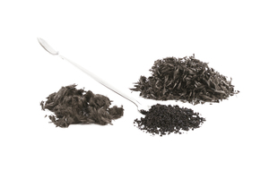
5.3 Blending of dusts and slurries into granules
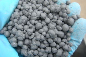
Blending dusts and slurries into granules and the process of granulating filter cake into a dust-free granulate (Figure 8) with good flow and storage properties, often combined with hot-air drying, can be a challenging task. These plants usually run in batch mode.
5.4 Recycling of aerosol cans
The aerosol cans (e.g. paint spray) are shredded, the propellants are captured, liquid and solid components (incl. metal parts from the cans) are fed into the mixer (Figure 9). Solvents are distilled off under vacuum, the mixer is emptied, and metal is separated out – leaving a granulate that is then fed to the SRF preparation and conditioning system. According to the assessment of the German Federal Environment Agency, this is the best available technology [9].
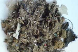
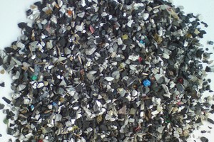
5.5 Processing of automotive shredder residue
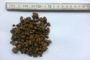
Shredder fluff (Figure 10, bulk material density of just around 60 kg/m³) is mixed with plastic-rich shredder granulate (Figure 11) and processed into a granulate – in the process the bulk density can be increased by a factor of seven. To do this, as the first step the shredder granulate is melted in the mixer at a temperature of around 250°C, and the fiber materials are then added and immediately incorporated. A practical and expedient solution for heating up the mixer is to use waste heat. By adjusting the speed of the mixing tool it is possible to control the size of the resulting granules (Figure 12) within wide limits. By adding coal, wood, or tire fluff as a third component it is possible to reduce the chlorine content to below 1% by weight. This process is known as the “ReGran” process [10].
6 When to use a horizontal mixer and when to use an Eirich mixer
Horizontal mixers are sufficient for most applications. If the mixing task is simple and the presence of coarser mineral or metallic impurities can be ruled out, these mixers will get the job done cost-effectively and sufficiently well enough.
Eirich mixers are used for challenging mixing tasks and in cases where the presence of coarser mineral or metallic impurities cannot be ruled out. The flexible mixing system, which is capable of processing all possible consistencies, is also advantageous if the charging material is changed frequently. The mixing system also enables the production of recovered fuels that are extruded and used in pellet form.
7 Outlook
The mixing systems ‘horizontal mixer’ and ‘Eirich mixer’ are used for the preparation and conditioning of SRF. The choice is defined by the specifics of the particular task in hand. The goal must be to ensure that cost-effective production can be ensured in the long term; for this reason it is important to not only consider the pure procurement costs. In addition to the supply of a mixer, customers are also often interested in the construction of a plant. The experience of the relevant supplier in the field of plant engineering should be queried here.
//www.eirich.com" target="_blank" >www.eirich.com:www.eirich.com