New PFR lime kiln process with blast furnace gas and oxygen


Production of high reactive lime is now possible with inexpensive blast furnace gas.
A new and innovative Parallel Flow Regenerative lime kiln process using 100% blast furnace gas achieves the same performance as a natural gas-fired PFR lime kiln; however, with significantly lower production costs.
The annual worldwide lime production amounts to approximately 400 million t and roughly 50% thereof is used for the iron and steel industry. Large steel mills often operate their own lime kilns and it can be assumed that up to 100 million t of lime are produced in integrated steel plants.
The most efficient and ecological way to produce high reactive lime and dolime is the use of modern shaft kilns.
Due to its unmatched thermal efficiency, the PFR lime kiln has established itself worldwide for this type of product. Therefore, PFR lime kilns are very common in steel mills.
They are mainly fired with natural gas, coke oven gas, converter gas, mixed gas and in some cases with low sulphur coal. Reasonable use of blast furnace gas for PFR lime kilns was not possible up to now.
Functional principle of the PFR lime kiln
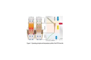
Due to the conditions of parallel flow of the kiln charge and the combustion gases in the burning shaft, the parallel flow regenerative kiln (PFR kiln) is perfectly suitable for the production of soft burnt, high reactive quicklime [1]. In addition, with regenerative preheating of the combustion air, the burning process provides for the lowest heat consumption of all modern lime kilns. Figure 1 illustrates the functional principle of this lime kiln. The differently coloured lines in the temperature profile at the right side of Figure 1 show the material as well as the air and the gas temperatures along the kiln.
The kiln charge, which is well screened limestone or dolomite, has a typical grain size of 50 to 100 mm but can also be smaller – 15 to 50 mm – or even larger – 60 to 150 mm. The kiln shafts are completely filled with the material to be processed and the kiln charge passes through the lime kiln at a speed of approximately one meter per hour.
The air and combustion gases flow through the void space, which is approximately 40% of the volume. Figure 1 illustrates the two phases of the gas flow. Lime is discharged continuously at the bottom end of the kiln shafts.
Fuel is only fed into one of the two shafts (burning shaft) respectively. In Figure 1 the fuel arrives in the left shaft, the burning shaft, whilst the right shaft operates as a non-burning or regenerative shaft. The fuel is fed into the kiln via a large number of burner lances, which are installed vertically in the material bed of the preheating zone. The bottom end of the burner lances marks the end of the preheating zone and the start of the burning zone. These burner lances feed and evenly distribute the fuel across the cross-section of the kiln shaft.
The fuel, together with the preheated combustion air fed in parallel flow through the material bed at the hot kiln charge, self-ignites.
Figure 1, on the right side, shows a typical temperature profile with the green line showing the temperature of the kiln charge, the blue line in the preheating zone showing the combustion air temperature, the blue line in the cooling zone showing the cooling air temperature and the red line showing the temperature of the combustion gases.
As the fuel is fed at the upper end of the burning zone, where the kiln charge is only preheated but not calcined, and the calcination process absorbs the largest part of the heat released from the fuel, the typical average temperature in the burning zone is approximately 950 °C. This is about 130 °C higher than the theoretical calcination temperature of the kiln charge.
The kiln works cyclically, usually with 90 to 130 cycles per day. The burning phase is characterised by the parallel flow of combustion gases and material in the burning shaft. The regenerative phase is characterised by the counter flow of hot gases in the non-burning shaft.
The combustion gases flow via gas channels from the burning into the non-burning shaft, where they perfectly transfer their heat to the kiln charge. Here, the preheating zone of the kiln is used as a regenerator, with the kiln charge as heat accumulator. This type of regenerator is insensitive to dust-laden or corrosive gases and at the same time offers excellent heat transfer characteristics.
Preheating of combustion air takes place in the preheating zone of the burning shaft when the combustion air passes the material bed in the preheating zone, which was preheated by the kiln off-gases during the previous operating cycle. The preheating of the combustion air makes the thermal efficiency of the kiln practically independent from the excess air factor. This then facilitates the setting of the specific heat input and the excess air factor to produce the required lime quality. A higher combustion air excess produces a shorter and hotter flame, a lower air excess leads to a longer and softer flame.
Main application of PFR lime kilns
The main application of PFR lime kilns is the production of high reactive, soft burnt lime.
As the calcination process (CaCO3+heat @ T > 820 °C CaO+CO2) consumes a large amount of heat, and most of the energy from fuel combustion is released at the upper end of the burning zone, the process temperatures in PFR lime kilns are relatively low.
For standard PFR lime kilns the volume of the burning zone is designed in such a way that the material can be fully calcined at an average burning temperature of 950 to 1050 °C.
Based on these boundary conditions, the retention time of the kiln charge in the burning zone is usually about 8 h.
These or similar process conditions are commonly used in PFR lime kilns with excellent results for high reactive lime.
Steel plant gases for the production of low sulphur lime
As calcium oxide is ideally suitable to absorb sulphur dioxide, all lime kilns with low off-gas temperatures absorb almost all the sulphur dioxide from the fuel combustion.
Due to the high thermal efficiency, the PFR lime kiln operates with the lowest off-gas temperatures of all lime kiln types. As a result, almost all the sulphur contained in the fuel is transferred to the product and a small amount to the bag house filter dust.
For the production of low sulphur lime, which is needed for the steel industry, not only the sulphur content in the raw material but also the sulphur content in the fuel must be taken into account.
Integrated iron and steel mills operate their own lime kilns in captive plants. These lime kilns are often fired with coke oven gas, converter gas or mixed gas and these gases contain almost no sulphur.
Blast furnace gas also contains no sulphur and the effective utilisation of BFG is important nowadays. The flaring off of excess BFG or producing electric power with low efficiency is not ecological anymore. Therefore, a new innovative process for PFR lime kilns fired with 100% BFG has been recently developed.
New innovative process for PFR lime kilns
Figure 2 shows the conventional process configuration of a PFR lime kiln, fired with natural gas or blast furnace gas. Combustion air is supplied to the burning shaft at the kiln top and fuel is fed through the burner lances at the burning shaft. The thermal efficiency of a PFR lime kiln, operating according to this process, is as high as ≈ 85% as long as the calorific value of the fuel is not too low.
As many steel plants produce the required quicklime in PFR lime kilns fired with different steel plant gases, this drop in efficiency is well known and has already been investigated [2]. The effect of lower thermal efficiency on a PFR lime kiln only becomes noticeable when fuel gases have a net calorific value of less than 7 MJ/Nm3. This means that besides natural gas (NG), coke oven gas, converter gas and mixed gas are excellent fuel gases for PFR lime kilns operating in accordance with the conventional process. However, most of the blast furnace gases (BFG) have a net calorific value of only 3.15 MJ/Nm3.
Using BFG in a PFR kiln operating in accordance with the conventional process leads to higher off gas flow, higher off gas temperature, lower production rate and lower thermal efficiency of the lime kiln.
Table 1 exemplarily shows a comparison of three different cases on a modern 500 t/d PFR lime kiln, operating in accordance with the conventional process, fired either with NG or BFG, as well as BFG according to the novel PFR lime kiln process.
With BFG used according to the conventional process, it can be seen that the production rate drops from 500 to 300 t/d, the specific heat consumption rises from 3430 to 4530 kJ/kg lime. The specific electric power consumption rises from 36 to 85 kWh/t of lime, the CO2 emission rises significantly and the required size of the bag house filter almost doubles.
All these negative effects disappear completely with the novel process, for which Maerz Ofenbau AG filed a patent application.
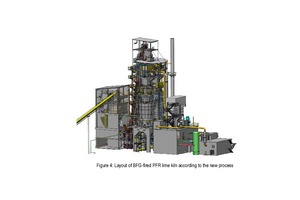
Figure 3 shows the flowsheet and Figure 4 the layout of a PFR lime kiln operating according to the novel process.
BFG is compressed to a pressure of 400 mbar by a high efficiency radial fan and is supplied to the top of the burning shaft. It passes the pre-heating zone of the burning shaft and is pre-heated to a temperature of about 700 °C.
Oxygen is supplied to the burner lances at the burning shaft. Self-ignition of the BFG occurs underneath the burner lances.
The adiabatic combustion temperature of the BFG-O2-mixture is very similar to the NG-air-mixture, which is used in the conventional process.
In addition, the mass flow of gases introduced into and flowing through the different zones of the PFR lime kiln are very similar compared with an NG-Air-mixture-fired PFR lime kiln. Therefore, the heat capacity flow ratio [2] is in the same range and as a result, all other process parameters are in the same range as well.
This novel process operation allows firing 100% blast furnace gas on a PFR lime kiln, with the same performance as a natural gas-fired PFR lime kiln.
Design challenges
To allow kiln operation during an outage of the blast furnace, a PFR lime kiln operating in accordance with the novel process should be equipped with an independent natural gas firing system.
When firing natural gas and in order to keep the investment costs as low as possible the BFG supply system, including the high pressure fans, should be used to supply combustion air to the kiln. Simultaneously, the oxygen supply and control system should be used for the supply of natural gas to the burner lances.
Double use of these systems is feasible but had to be analysed in detail. For this reason a comprehensive risk analysis for functional safety and a detailed explosion protection concept were prepared, taking the different process operating modes into consideration.
The outcome of the risk analysis showed that a nitrogen purging system for the different gas supply systems as well as for the lime kiln is required.
At the end of the burning cycle, the BFG flow to the kiln is interrupted, resulting in the kiln top of the burning shaft being full of blast furnace gas. To avoid BFG emissions to the atmosphere when changing the burning shaft, this gas needs to pushed down to the burning zone with nitrogen. During this purge time, the oxygen is still supplied through the burner lances at the burning shaft, to provide complete and safe combustion of the BFG inside the burning zone.
Before and after changing from natural gas to blast furnace gas all fuel and combustion air supply systems, as well as the oxygen supply system, need to be purged with nitrogen as well.
CAPEX and OPEX
The CAPEX of a PFR lime kiln fired with blast furnace gas and natural gas is only about 10% higher compared with a PFR lime kiln fired only with natural gas.
As far as OPEX is concerned, all relevant consumption figures are shown in Table 1 and can easily be calculated, depending on the price of the different fuels and oxygen. In steel plants excess blast furnace gas is often flared off. In such cases the cost of fuel is zero and in most of the steel plants cryogenic oxygen production prevails and the production costs of the oxygen are much less compared with the fuel costs of a natural gas-fired lime kiln.
Conclusions
Production of high reactive quicklime in a PFR lime kiln using blast furnace gas and oxygen is a viable solution which is both economically and ecologically interesting for captive steel plants operating their own lime kilns. The thermal efficiency with the new innovative process is about 85% and provides optimal conditions for the sustainable use of blast furnace gases.