Responsible refractory adaptation for sustainable cement clinker production: Green Challenge accepted
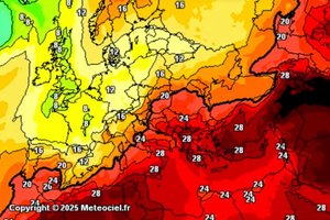 Meteociel.fr
 [2]
[2]
 Authors
 taken from [12]
 Authors
 Authors
 Authors
 Authors
 Authors
 Authors
 Authors
 Authors
 Bildquelle Re magnis denda abo. Namenim agnatqu id
 Bildquelle Re magnis denda abo. Namenim agnatqu id
![Table 3 Investment cost and their impact on CO2 savings for various measures (basis of data from [21]](/uploads/images/2025/w300_h200_x600_y203_Table_3-e42e9a633ceba8ea.jpeg) Bildquelle Re magnis denda abo. Namenim agnatqu id
Bildquelle Re magnis denda abo. Namenim agnatqu id
 Bildquelle Re magnis denda abo. Namenim agnatqu id
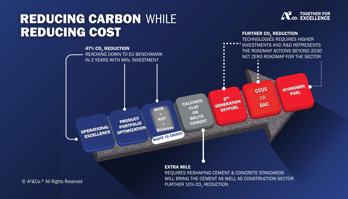
The energy-intensive mineral industry is closely monitored due to its carbon impact, mainly CO2 emissions. Actions are taken by the cement and lime industry to reduce their amount by various measures, but most of them are still in their development phase, are costly, or may affect the properties of the final product, cement.
Focus is put on carbon capture and storage/utilisation, which grants the highest reduction of CO2 and may contribute most to the goals of the GCCA and various political stakeholders, but is very cost-intensive and needs special infrastructure. It also requires societal acceptance and a clear political framework. Consequently, it is inevitable to reduce the amount of CO2 for cement and lime burning. As approx. 10% of process heat is lost via the kiln shell, refractory producers have found a way to reduce the amount of these heat losses and retain the heat inside the kiln system. Fuel input is reduced and/or thermal processes in the preheating system are enhanced. A sophisticated, patented microstructure allows the reduction of thermal conduction utilising air as insulating agent in the refractory brick, without compromising the crucial properties for successful kiln operation. Thermal calculations show that by installation of these basic and non-basic linings annually about 3500 t of coal and 8000 t of CO2 can be cut, with the respective positive impact on expenditure. This CO2 does not have to be captured, processed, transported and stored. Considering not only the refractory material, but also its influence on expenses and sustainability, the installation of an energy- and emission-saving lining is technically (proven by TRL 9), economically and ecologically inevitable. Each ton of CO2 which can be prevented reduces cost and impact on the environment. Overall, installation of energy- and emission-saving refractories additionally results in cost savings, which must not be bypassed to meet the carbon challenge.
1 Introduction based on climate requirements
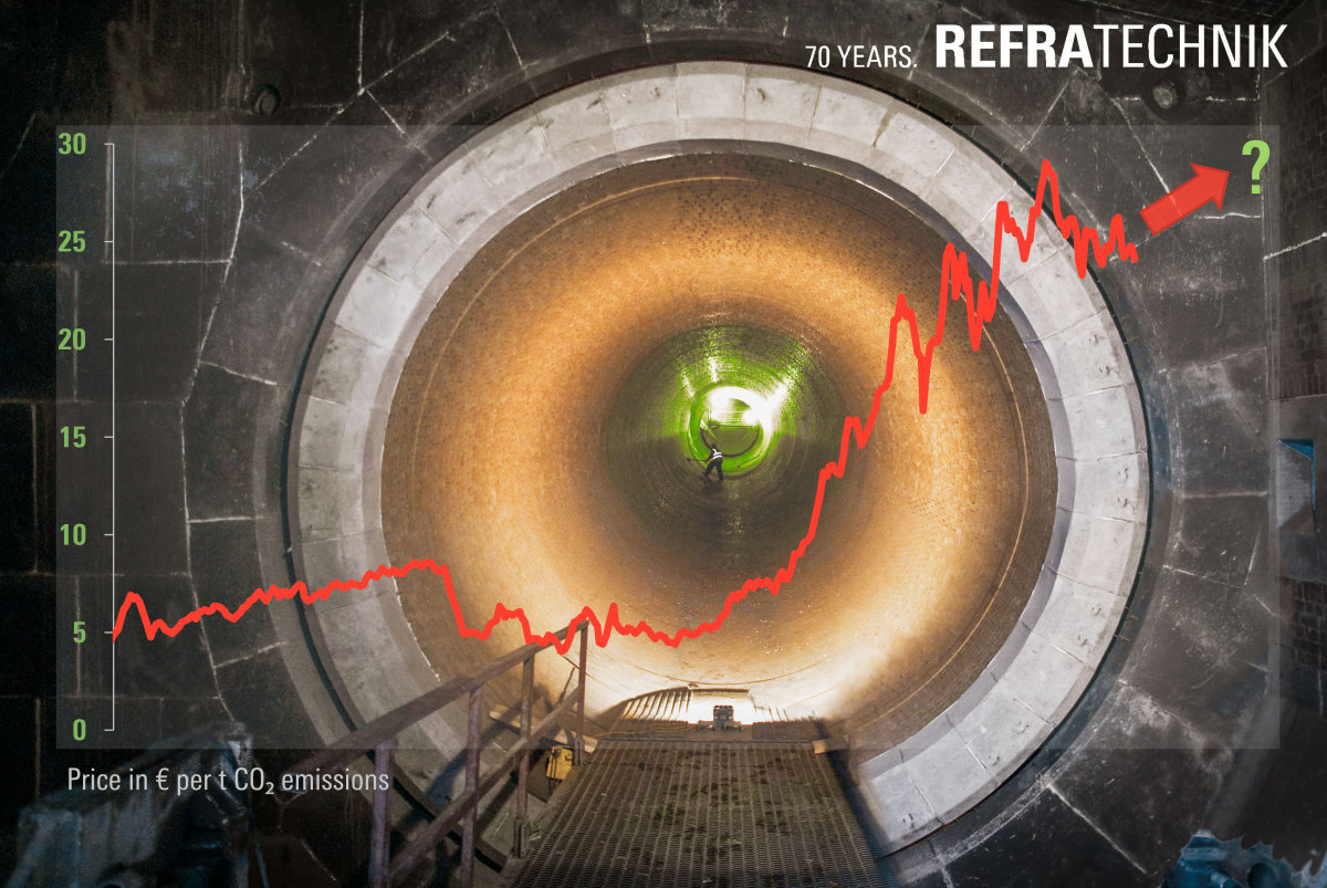
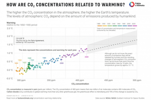
It is becoming increasingly obvious that global warming is proceeding (Figure 1), and its impact is evident everywhere: wildfires in Canada, Greece and Spain, melting of glaciers, increasing intensity of tropical storms, etc. Although global warming is still not recognised by some parties, the correlation between global temperature increases and CO2 concentration in the atmosphere is striking and beyond any discussion ([1], [2], Figure 2).
To ease the stress on our planet and its population, the politically stipulated measures (Kyoto protocol 1997, Paris Agreement 2015) still lack complete success due to slow implementation caused by technical and political obstacles.
Apart from each’s personal responsibility and behaviour, the industry as a whole is requested to reduce greenhouse gas emissions, i.e. mainly of CO2, but also of methane, nitrous oxide, ozone, and water vapour. Since the beginning of the Industrial Revolution (around 1750) human activities have increased the carbon dioxide levels by over 50% and methane levels by 150%. In the atmosphere, carbon dioxide emissions are causing about three-quarters of global warming, while methane emissions cause most of the remainder [3].
The commitment of the European Union is to reduce emission by >55% by 2030 and to achieve carbon neutrality by 2050.
2 Cement Industry’s Focus on Sustainability
Political and economic pressures are imposed on the cement (and to a similar degree on the lime) industry over time (Figure 3). It is postulated that cement production is responsible for approx. 8% of the global CO2 emissions. Therefore, e. g. China as the world’s largest cement producer and consumer has modified its GB16780 (“The Norm of Energy Consumption per Unit Product of Cement”), to define and reduce the energy, fuel and electricity consumption [4].
The measures of global and local cement companies, also postulated by the GCCA and which can be derived from the sustainability reports of globally acting cement producers, are mainly the following:
1. Carbon Capture (Utilisation) and Storage (CC(U)S) is the main method to capture CO2 and store it in appropriate geological formations such as depleted gas/oil fields or saline aquifers. Undoubtedly a strong tool, but very investment-intensive and difficult to apply. A pipeline network is necessary, or alternatively an elaborate train logistics, as each day approx. 2000 t CO2 have to be transported and processed for a single kiln, amounting to approx. 650000 t CO2/a. In Europe, Norway is leading in the deposition of CO2 in saline aquifers under the North Sea [5]. Calculated costs for CCS can sum up to € 150–250/t CO2 depending on the plant location
2. The reduction of the clinker factor reduces carbon dioxide emissions, as less cement clinker in the final cement is used. To maintain the cement quality and properties, a higher content of alite in the clinker may be necessary, which again influences emissions and clinker production parameters
3. Use of Supplementary Cementitious Materials (SCMs). In the past, mainly fly ash and blast furnace slag have been used, but due to their decreasing availability calcined clay is qualified as replacement. Calcined clay would also contribute to the carbon footprint due to a thermal activation, but to a way lesser extent than clinker. Therefore mechano-chemical activation methods are under development
4. Improvement of the overall efficiency, including kilns, coolers, mills, classifiers, even though the cement production process is already highly optimised. Older kiln plants are modernised on regular basis and comply with modern technology. The left gains in efficiency are therefore low
5. Use of alternative fuels is already state of the art, especially in Europe (substitution rate for classical fuels (gas, coal) in Germany is 76%). The biogenic fraction of the resulting CO2 emissions is accounted as carbon neutral and consequently not charged for with carbon taxes. Alternative fuels are available in large quantities, as their sources are manifold. Also, the burning technology is available, and solutions for technical challenges are state of the art, e. g. [9-11]. The type and availability of alternatives fuels might change in future with increasing the recycling rate for certain substances
6. Thermal processes with hydrogen or electricity show only a limited potential for decarbonisation due to high demand of heat required
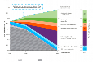
The net-zero-plan of the cement industry is mirrored in the goals of the Global Cement and Concrete Association (GCCA) (Figure 4) [12]. A lot of effort is put into CCS/CCUS, with the beforementioned requirements on logistics, political decisions, infrastructure and the resulting CAPEX. Even after full decarbonisation has been achieved, the price of emitting CO₂ in the EU ETS will continue to increase due to the phase-out of free allowances and the resulting shortage of available certificates on the market. Against this background, improving the refractory lining, alongside the aforementioned measures, could be valuable in helping to avoid CO₂ emissions and the associated CCUS costs.
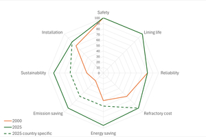
While in 2000 reliability and lining lifetime were mostly in focus, in recent years the reduction of CO2 emissions and the resulting sustainability came more into focus. Furthermore, emphasis is laid on refractory cost, but without considering the economical worthwhile total cost of ownership (TCO).
3 GHG emission classification for the cement industry
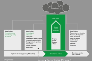
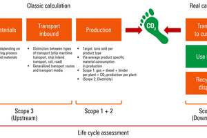
To appreciate the measures of carbon dioxide reduction for the cement industry, Figure 5 gives a description of its influences for cement producers. Scope 1 describes the direct emissions by the cement clinker production process. Scope 2 and 3 upstream (both indirect) describe the upstream activities (e. g. transportation, travelling, supplier activities and products), while Scope 3 downstream activities comprise the use of cement, mostly its performance in concrete also as a CO2 sink.
The production facility which adds most to CO2 emissions is naturally the clinker burning process. Thanks to efforts from kiln, burner and refractory manufacturers, combined with the expertise of cement producers, the clinker burning process is highly efficient nowadays regarding technical and environmental issues.
The need for energy savings and CO2 emission reductions has also been recognised by the refractory industry [13-15]. Refractories are the only barrier between the hot kiln gas atmosphere/hot clinker and the steel kiln shell and the environment. Thermal insulation, apart from its function as a heat exchanger, is the original purpose of any rotary kiln refractory lining.
Regarding the targets of the cement industry, it would be rather advisable to aim for an emission-reducing solution involving both controls, namely Scope 1 and Scope 3 upstream. Here, emissions can be remarkably reduced, as the latter is Score 1 of the refractory producer, the improvement of which would benefit all environmental targets.
4 Kiln lining contribution to increase kiln efficiency
Because of the necessity of further thermal insulation to increase the efficiency of the clinker burning process, old concepts were re-discovered, e. g. two-layer bricks (consisting of a dense wear layer and an insulation back-up layer, pressed into one brick) or 2-layer linings (consisting of two separate layers).
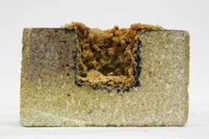
Two-layer-bricks are regionally available and can contribute to retain the heat inside the kiln (Figure 6). Their production process is intricate, and the production capacity is limited. Due to mechanical effects by the rotating kiln and thermal shocks, separation between the two layers during service is repeatedly observed. Technically, this is a dense refractory brick, requiring also a high quantity of raw materials, counteracting the Scope 3 upstream emission reduction in cement production. Furthermore, the two-layer structure impedes the recycling of used bricks.
Two-layer linings are standard in the lime industry, with smaller kiln dimensions, lower temperatures and slower rotation speeds. They are very effective in lowering the kiln shell temperature and thus the energy input. The two-layer structure, which must remain stable during kiln rotation, needs a tight installation, that must not spall during service to prevent axial and circumferential loosening of the lining. A 50% longer installation time and the need for a skilled installation team (which is nowadays not a matter of course) are major drawbacks of this lining type, additional to the high material input also affecting Scope 3 of cement production.
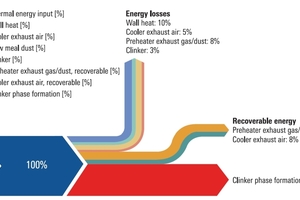
The kiln shell temperature indicates the amount of heat retained in the kiln. The lower it is, the more heat is kept in the kiln and is available for more clinker production, a reduction of fuel input and an enhancement of processes in the preheater, e. g. raw meal decarbonisation.
Due to the ever-increasing global temperatures (Figure 1), environmental and thus sustainability considerations are becoming increasingly important. A major impact on the environment are the energy losses through the kiln shell during service, as the remaining energy is used for the cement clinker production process (Figure 7).
Striking are the wall heat losses, which cannot be prevented but thoroughly reduced by the refractory lining.
The effect can be measured mainly by the determination of the kiln shell temperature. Although this parameter is affected by several factors (coating, burner irregularities, fuel inhomogeneities, etc.), it is the assured indicator of energy efficiency and the related emission saving.
Attempts have been made in the past to save energy of the rotary kiln process, but only specially developed insulating fireclay bricks have been successful [16].
5 Refractory Development as Driver for Sustainable Cement Production
A patented groundbreaking development from 2014 was already introduced into the market [17-18], and was also recognised by the lime industry. It was a completely new design for basic and non-basic bricks towards a fine-grained structure, pushing refractories more towards technical ceramics. Only in this way was it possible to maintain the essential refractory properties while increasing the insulating properties by more than 20%. This so-called ES lining (emission and energy saving) is designed to reduce the amount of climate noxious gases by reducing energy input and simultaneously saving costs by achieving a similar lifetime to that of standard linings.
5.1 Design of new refractory generation
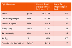
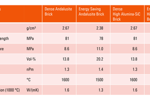
Density and porosity directly influence other refractory properties like strength, elasticity, refractoriness under load etc. Strength and refractoriness were formerly negatively affected when porosity was increased.
To overcome this limitation, a new microstructure, completely different from those used up to date, was developed. It is characterised by a fine-grained structure and a porosity in the range of 20 to 25%, up to now unusual in typical basic and non-basic materials for working linings of rotary kilns (Figure 8).
Strength and refractoriness are barely influenced by this structural modification, they are in the typical and well-proven range of bricks for rotary kilns (Figure 9, Figure 10). Due to the increased porosity, the low conductivity of air is used to reduce thermal conduction and heat losses during refractory service life.
The alkali resistance of the insulating alumina-silica bricks also is similar to that of the already used high-performance SiC-containing products, despite their higher porosity. This is proven by the well-known cup corrosion test at a temperature of 1100 °C with K2CO3 as the corrosive agent. Figure 11 shows the prevention of the undesired alkali corrosion reaction.
5.2 Lining pattern with new generation bricks
As the performance-relevant properties of bricks with high porosity are met, these refractories are installed to reduce costs, because they counteract CO2 emissions and energy losses. As the firing processes in the cement industry with varying raw materials and fuels make it difficult to experimentally verify the savings (apart from the fact that the kiln shell temperatures are reduced), simulations were performed by the ‘Verein Deutscher Zementwerke’, VDZ (German Cement Manufacturer’s association) [19-20].
For this calculation, a BAT (best available technique) state-of-the-art rotary kiln with a production capacity of 5000 t clinker/day was defined, with single-string 5-stage preheater, inline calciner and grate cooler. The kiln tube is 75 m long and has a diameter of 5 m. While the kiln is fired with coal dust, the calciner is fired with a combination of coal dust and an alternative fuel mix (fluff, animal meal, mechanically dewatered sewage sludge).
For the calculation, two refractory lining patterns were evaluated, reflecting typical and increased chemical loads. This included the whole range of relevant basic (magnesia-spinel) and non-basic (bauxite, mullite, fireclay) refractories necessary for a successful rotary kiln operation
Exemplarily, demanding kiln conditions are characterised by thermochemical influence due to the use of alternative fuels and raw materials as well as severe process conditions. Mostly, a mechanical strain is present as well, e. g. caused by kiln shell deformation, ovality, axial distortion.
Therefore, a mechanically and alkali-optimised lining concept includes high alumina alkali-resistant brick grades in the calcining and safety zones. In the transition zones and burning zone, basic brick grades are installed (Figure 12).
In the energy saving and alkali-resistant lining concept, the safety and calcining zones are lined with the new insulating fireclay and high-alumina bricks. The transition zones and the burning zone are lined with the emission-saving magnesia-spinel bricks.
5.3. Calculated Results for Emission Savings
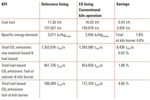
Table 1 shows the results for emission and energy saving for regular kiln operations, as calculated by the VDZ [20]. The total fuel-savings sum up to more than 3400 t/a of coal, and the resulting CO2 savings on the burner sum up to 8680 t CO2/a, being 4.7% of the fuel-based CO2 emissions at the main burner. The total fuel-based emission savings are 1,9%. The resulting cost savings can easily be calculated and depend on the fuel price. Calculations for demanding conditions are similar.
A refined model including refractory wear up to a remaining brick thickness of 110 mm is reached, and changes in thermal conduction due to infiltration of alkalis, gives similar results [Table 2]. Naturally, the absolute figures are higher, but the saving effect is alike.
Particularly remarkable are the savings in weight, 8% less material is required for the kiln lining, which has a non-negligible effect on amount of purchased refractories. Consequently, less electricity is needed to operate the furnace, there is less need for external cooling of the furnace wall with fans, and health and safety aspects are improved.
From a cost and environmental perspective not only emissions (including emission certificates) have to be considered, but also the reduction in fuel purchase. The expenses can easily be cut by more than € 1.5 million given the lower costs of fuel and emission certificates (at a price of € 75/t CO2, this alone amounts to nearly one million euros). Each ton of CO2 which can be prevented does not need to be captured, processed, transported, and stored. CO2 prevention is an active contribution to responsible management of cost and environment.
With its high technology readiness level TRL 9, the emission and energy saving concept not only fulfils the industry’s sustainability promises but also meets the requirements for cost competitiveness.
The effect complies with the targets of the cement industry. It is in the range of the annual reduction targets, as can be read from the sustainability reports of several cement producers. This reduction does not need any additional investment. Regarding total cost of ownership, even a significant cost reduction can be achieved, exceeding the price of the refractory lining itself.
The measures of the cement industry (Ch. 2) are accompanied by high investment costs summing easily up to several million euros per plant. The effect on efficiency varies [Table 3.] It is highly appreciated that a simple measure like switching to an emission-friendly refractory lining at no extra cost results in an economically advantageous situation. This means not only avoiding extra OPEX and CAPEX costs but also making remarkable savings on CO2 certificates (at least in regions where this applies, which will increase over the next years) and on fuel. It goes without saying that the significant cost reduction brings with it increased competitiveness. Additionally, even if the measures shown in Table 3 are taken, the benefit of an ES lining always comes on top. Each ton of CO2 which can be prevented reduces cost and impact on the environment.
Overall, installation of energy and emission saving products results in significant economic and ecological savings, which must not be bypassed to meet the carbon challenge.
5.4 Considerations on the Carbon Footprint
The carbon footprint is a parameter which describes the emission impact on the environment and is a new decisive KPI for the industry. The classical calculation considers the production emissions (Scope 1) as well as energy-related emissions (Scope 2). When compared to other figures, it fails when various product groups are compared, e.g., dense refractories with porous materials. It is more meaningful and robust to report emissions per running metre installed, e.g., in the case of rotary kilns. Even more robust are the statements when Scope 3 as a whole is considered. This includes the raw materials (essential for the carbon footprint of refractories) as well as their use and beneficial performance in the kiln [Figure 13]. In the case of energy and emission saving products, the CO2 emissions saved far exceed the emissions generated during the manufacture the product itself. The effectivity is much higher than for two-layer-linings, two-layer products, or even materials produced with recycled raw materials.
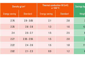
While CO2 emissions per ton are comparable for dense and the new insulating products, the latter require roughly 10% less material. This keeps their environmentally relevant carbon footprint much lower (Table 4). Not only the emission for the product is important, but even more the savings that can be achieved through its use (Table 1, Table 2). A comprehensive overview is given in Table 4, where the savings in weight (contributing to a lower carbon footprint Scope 1, 2, and 3 upstream) as well as thermal conduction (contributing to a lower carbon footprint Scope 3 downstream) are shown.
This explains the tremendous effect that can be achieved by the application of the Energy Saving concept for refractory manufacturer and user.
As a result, the ES lining not only shows an improved product carbon footprint. Even more importantly: the process carbon footprint with the refractory product, including its use in cement production, is remarkably reduced. The shared footprint for both the refractory and cement producers is lowered.
The high relevance of the claim addressed in this publication is evident from the scaling effect with emission and energy saving refractory from one rotary kiln to the total industry. A calculated amount of up to 14 million t of CO2 may be avoided if all kilns were equipped with these refractories, although some kilns may require a lining as suggested in [10] and [11].
A major advantage of the so-called ES lining is that there are no additional costs, as a refractory lining has to be installed anyway. Installation can be carried out as usual; no other skills or tools are required (unlike with a 2-layer-linning, for example).
Considering not only the refractory material installed, but also its influence on costs and sustainability, the installation of an energy- and emission-saving lining is technically, economically and ecologically unavoidable.