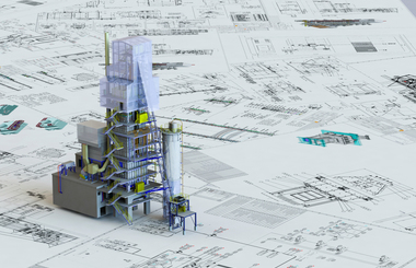
New and innovative Maerz PFR lime kiln for Kalkfabrik Netstal in Switzerland


Maerz Ofenbau AG built a new PFR lime kiln with a direct cross-over channel for the production of quicklime with a very low residual CO2 content and very high reactivity in Kalkfabrik Netstal/Switzerland. The aftercooler prevents the otherwise unavoidable recarbonization in the cooling zone and enables the production of lime with a residual CO2 content of 0.5% in a PFR kiln with direct overflow channel.
1 Introduction
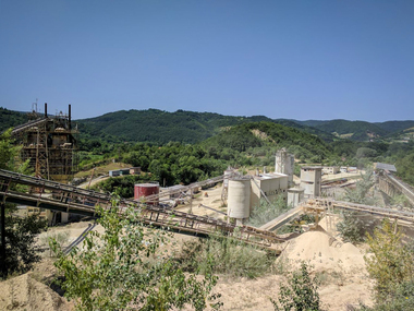
The first lime plant in Netstal/Switzerland became operative in 1900. Since 1992 the operational management of Kalkfabrik Netstal lies with Mr. Heinz Marti. In 1994 the first 200 t/d Maerz PFR lime kiln with oil firing was commissioned in Netstal. In 2013 that Maerz kiln was converted to natural gas firing. The lime products produced in Netstal have always been world class. That is, on the one hand, due to the especially pure limestone and on the other hand, due to the production process, which has continuously been developed and improved over time.
The new 200 t/d Maerz PFR lime kiln was commissioned in October 2020. To meet the steadily increasing market requirements, a new PFR lime kiln with aftercooler and natural gas firing was used. This new lime kiln was designed for especially low residual CO2 content and especially high reactivity of the quicklime. Hence it was necessary to develop a PFR lime kiln with a direct cross-over channel, enabling this product quality to be produced permanently. The disadvantageous recarbonisation of the quicklime in the cooling zone, which was inevitable in previous PFR kilns with a direct cross-over channel, had to be avoided by introducing a new process.
2 Realisation of the new PFR lime kiln with aftercooler
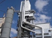
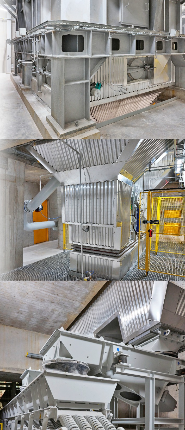
The kiln project began with the signing of the contract on 30.08.2018. Construction begin was on 13.01.2019. The kiln was ignited on 16.10.2020 and could already be handed over to Kalkfabrik Netstal on 12.11.2020, following the successfully completed acceptance test (lead picture).
Compared with other kiln projects, the time period between the signing of the contract and construction begin was a little longer. This enabled the design of a new PFR kiln with aftercooler.
On behalf of Kalkfabrik Netstal, the contract for the erection of the foundations and buildings was awarded to a local building company. The kiln, including the kiln house in which the kiln is located, was built and commissioned by Maerz as the general contractor.
Due to the narrow access road to the factory site, no large kiln pieces could be delivered. The kiln shafts were prefabricated in a workshop, divided into transportable pieces and delivered on trucks. These parts were then assembled into larger units in the pre-assembly area.
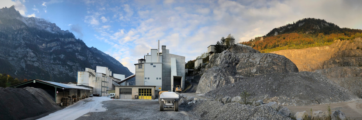
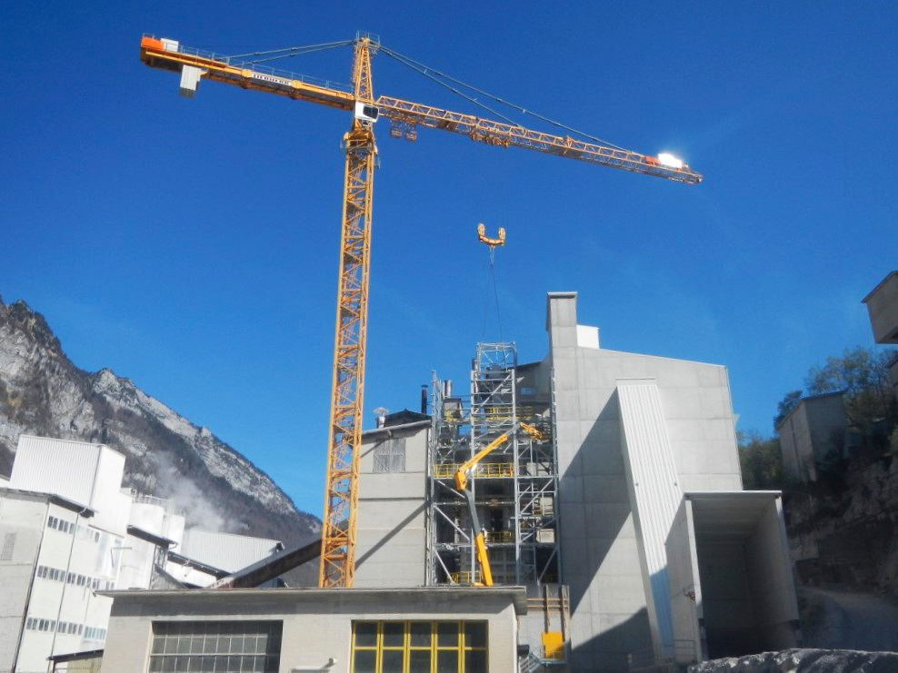
The tight space between the limestone silos, the lime silos, the limestone crushing plant and the company workshop posed a major logistical challenge. The kiln was therefore mainly assembled using a rotating tower crane (Figure 1).
The Corona pandemic complicated the processes during production and assembly in many respects. Nevertheless, the assembly could be completed without any interruptions and the kiln plant was handed over to Kalkfabrik Netstal on schedule.
3 The kiln
Now that Kalkfabrik Netstal is able to cover its entire lime requirements with this new kiln, it is important to achieve the greatest possible utilisation of the quarry. To this end the limestone is crushed to about 100 mm, with two double roller crushers in a two-stage crushing plant, which was erected by Maerz in 2010. Subsequently, the 15 to 40 mm fractions and the 40 to 100 mm fractions are sieved and washed. Both fractions are fed to the kiln in equal parts. A utilisation factor of about 85% of the limestone mined in the quarry is achieved due to the use of toothed double roller crushers as well as a very wide grain size range in the PRF kiln.
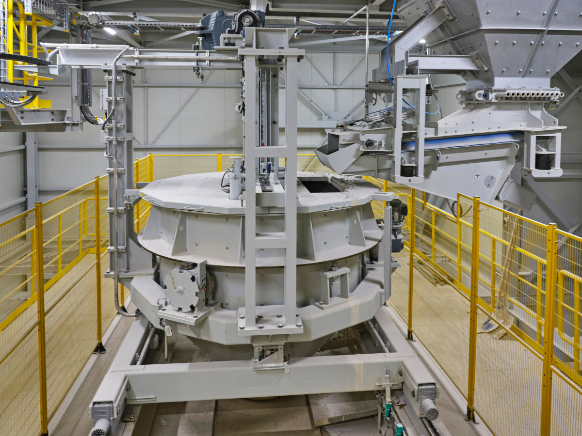
To achieve the best possible grain distribution in the kiln shafts, a rotating bucket feeder as shown in Figure 2 is used. The feeder moves back and forth on rails between the two kiln shafts and the loading position in the middle of the kiln. The rotating bucket is additionally equipped with a weighing device, so that the weight of the charged stone can be precisely registered. While the rotating bucket is being filled it is rotated so that the different sized limestone can be evenly distributed in the rotating bucket. The lime kiln is recharged at the regenerative shaft during the burning time. To this end the pressure in the kiln top of the regenerative shaft is reduced with the help of the exhaust fan, then the shaft’s closing trap is opened and the rotating bucket is emptied into the kiln shaft by pulling out the sealing plug.
The kiln’s charging system is located below the rotating bucket feed and comprises the tops of the kiln shafts, the shaft shutters, the exhaust gas trap, the stone steering devices and the level measuring devices (Figure 3). The stone steering devices essentially work as remotely adjustable chutes, which steer the limestone sliding out of the rotating bucket either towards the left or the right side of the kiln shaft. The combination of the rotating bucket and the stone steering device within the kiln top makes it possible to fill the rectangular kiln shafts largely homogeneously when viewed across the shaft cross-section. This is an important prerequisite for even temperature distribution in the burning zone, as the even distribution of the combustion air can only be influenced by the grain distribution of the limestone.
In comparison with previously built PFR lime kilns, a larger number of burner lances, with respect to the shaft cross-section, were incorporated. Allocating this many burner lances was difficult as they had to be arranged in a manner which would not allow the charge to form bridges in the kiln shafts. Due to the large number of burner lances however, the fuel can be very evenly distributed across the shaft cross-section. This leads not only to a homogeneous temperature distribution in the combustion zone, but also to a complete combustion at low flame temperatures and thus also to extremely low pollutant emissions as well as a high reactivity of the quicklime.
The geometry of the refractory lining was chosen so that despite thermal expansion, the charge cannot form bridges at any time. This leads to an absolutely even bulk movement in the kiln shafts and a homogeneous calcination of the limestone.
Avoiding what in these PFR kilns was previously inevitable, namely the recarbonisation of the quicklime in the cooling zone, required a complete redesign of the lower area of the lime kiln.
The kiln’s discharge tables had to be designed for higher temperature loads than usual. It was also necessary to design the supporting structure in a way to avoid overheating. The lining in the cooling zone was adapted to the special temperature profile in this area. Once the entire lime kiln, including the aftercooler, was erected inside the kiln house, it was necessary to insulate all hot surfaces and to ensure adequate ventilation.
4 Preventing recarbonisation in the cooling zone
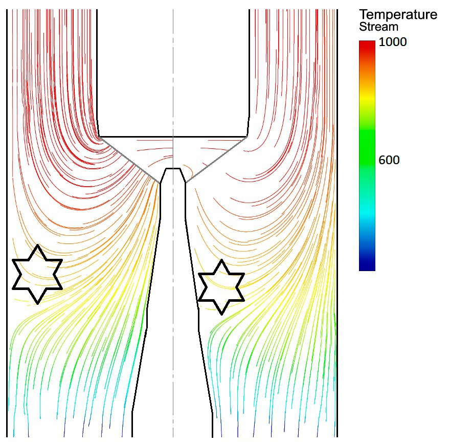
Figure 5 shows the typical streamline flow pattern of a PFR lime kiln with a direct cross-over channel as well as the prevailing temperatures in the conventional mode of operation without an aftercooler. Previously inevitable recarbonisation takes place in the areas with the star-shaped markings. In these areas the temperature of the quicklime is below the calcination temperature and the CO2 of the flue gases flowing through these areas react with the already calcined quicklime and in turn form calcium carbonate: CaO + CO2 CaCO3.
To prevent or drastically reduce recarbonisation in these areas, the temperature of the quicklime there must be set higher than the calcination temperature. This is achieved by significantly reducing the cooling air flow introduced into both kiln shafts from below. When implementing this new process however, the quicklime must be discharged from the kiln hotter than previously usual. This requires, on the one hand, a corresponding design of the lime kiln and on the other hand, the subsequent cooling of the charge outside of the lime kiln.
Figure 6 shows the increase in the residual CO2 content caused by recarbonisation. The picture on the left shows operation according to the previous state-of-the-art technology and the picture on the right, operation according to the new patented [3] process with an aftercooler.
For the development of this new PFR lime kiln with aftercooler, the most modern simulation methods [1, 2] were used. They were developed at the Ruhr University Bochum in Germany in the Department of Energy Plant Technology under the leadership of Prof. Dr.-Eng. Viktor Scherer.
Due to the large reduction in cooling air, the exhaust gas temperature is lower in comparison with an operation using previously normal amounts of cooling air. This means that despite higher lime temperatures, there is no additional heat loss in the lime kiln.
In order not to drop below the minimum temperature required for the operation of the exhaust gas filter system, the exhaust air from the aftercooler is added upstream of the kiln exhaust gas filter. The fine lime in the cooling air is separated by a cyclone separator and then fed back into the product.
5 Operating results
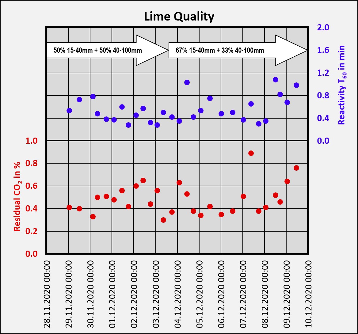
Lime quality as depicted in Figure 7 was attained during normal operation mode of the kiln with nominal capacity and charging with a stone grain size of 15 – 100 mm. The specific heat consumption averaged 3550 kJ/kg lime and the specific power consumption 30 kWh/to lime.
6 Summary
In Kalkfabrik Netstal/Switzerland, Maerz Ofenbau AG, as general contractor, built a new PFR lime kiln with a direct cross-over channel for the production of quicklime with a very low residual CO2 content and very high reactivity. The kiln produces the entire amount of lump lime required at this location and is therefore fed with a very large grain range from 15 to 100 mm. It was previously not possible to produce such a high product quality in such PFR lime kilns. The new PFR lime kiln is equipped with a downstream cooler for quicklime, which allows for the new patented [3] mode of operation preventing or greatly reducing the otherwise inevitable recarbonisation in the cooling zone.