Sustainable recycling of marine dredged sediment in slag-fly ash geopolymer at laboratory scale
To ensure smooth and safe traffic flow within the coastal port, the fairway must maintain adequate water depth. However, tides, siltation, and river sedimentation commonly lead to sediment accumulation and consequently a decrease in water depth, necessitating regular dredging operation. The silt and sediment generated from these activities in port engineering and waterway maintenance are referred to as marine dredged sediment (MDS) [1–3]. In recent years, coastal provinces in China, such as Guangdong and Jiangsu, have produced large quantities of MDS annually due to projects including land reclamation for urban construction and port development, and the construction of offshore wind farms involving seabed excavation and cable laying. MDS is a fluid-solid waste characterized by high moisture content and a wide range of particle sizes, while also containing certain harmful substances such as pathogenic microorganisms and heavy metals [2]. Although researchers have explored techniques for the resource utilization of MDS in construction materials, such as road construction, brick-making, ceramsite production, and concrete manufacturing, the current utilization capacity still cannot meet the annually growing demand for recycling MDS [4–8]. The primary treatment methods currently employed for MDS still involve direct approaches like ocean dumping, landfill, and reclamation (as shown in Figure 1), which are prone to causing secondary pollution [2, 4]. Consequently, the sustainable recycling of MDS has become a technical challenge in port construction worldwide [9].
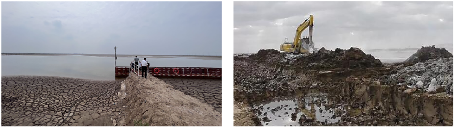
Figure 1 Photographs of MDS stockpiling and landfilling sites in the Binhai Port, Yancheng City, Jiangsu Province, China
With accelerated industrialization and urbanization, concrete has been extensively used in infrastructure construction. Such material also provides an effective pathway for the large-scale recycling of various industrial solid wastes [10]. Currently, fly ash (FA) obtained from coal-fired power plants and ground granulated blast furnace slag (GBFS) obtained from iron smelting industry have become indispensable supplementary cementitious materials (SCMs) used as replacements for ordinary Portland cement (OPC) in concrete manufacturing [11]. Meanwhile, other solid wastes, such as construction and demolition waste and metal tailings, have also demonstrated broad recycling prospects in concrete. If MDS can be utilized as SCMs to manufacture concrete, it could be locally consumed during port construction, thereby addressing both the issue of harmless disposal and reducing the high costs associated with its transportation [1–3].
However, the high content of chloride ions (Cl−) present in MDS, which can reach 0.1–0.3%, far exceeds the safety thresholds specified in concrete-related standards, thereby exhibiting a great potential for accelerating the corrosion of embedded steel reinforcement [12]. More importantly, MDS exhibits low pozzolanic reactivity, and consequently, its incorporation significantly affects the strength development of cement binder [7, 12]. This leads to low recycling rates in traditional OPC-based concrete. Chu and Yao [3] reviewed recent literature on the utilization of MDS in concrete and proposed a strength development model with the MDS incorporation recognized as the most critical factor influencing compressive strength of concrete. It was noted that it was difficult to achieve strength values above 40 MPa when the incorporation ratio exceeded 25%. Dang et al. [6] calcined MDS at 650–850°C for 5 h to produce a fine pozzolanic powder, and used it as an OPC substitute in the preparation of mortar. When 33% of OPC was replaced by the calcined MDS, the 28-day compressive strength could reach 50 MPa. However, such high-temperature calcination involves high energy consumption. This should not be performed for the sustainable disposal of this type of solid waste. Therefore, the application as SCMs in traditional OPC-based concrete is currently unable to meet the demands for large-scale recycling of MDS.
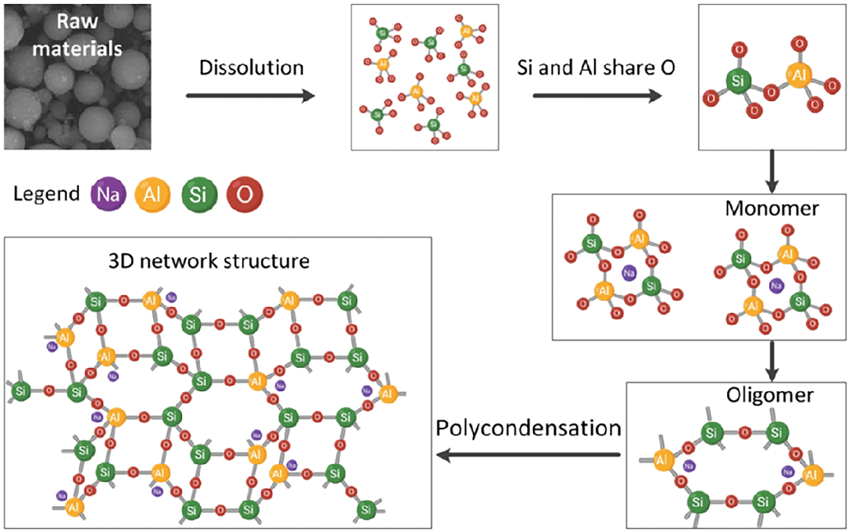
Geopolymer is a cementitious material synthesized from the alkali-activation between silicon- and aluminum-rich industrial solid wastes (e.g., FA and GBFS) and alkaline activators (e.g., NaOH or sodium silicate solution) [13]. The primary strength-contributing hydration product formed in geopolymer is recognized as sodium-containing calcium aluminium-substituted silicate hydrate (C-(N)-A-S-H) gel phase [14]. Owing to the rapid strength development, dense microstructure, low permeability, and excellent chemical resistance, this material has become an ideal medium for the resource utilization of solid wastes [15–17]. Rashad and Essa [18] reported that incorporating waste ceramic powder into alkali-activated GBFS enhanced the thermal stability. Xu et al. [19] demonstrated that using copper slag together with GBFS in geopolymer provided a filling effect to reduce total porosity and volume of harmful pores in the binder. Fernández-Jiménez et al. [20] confirmed the feasibility of using hydrothermally treated sewage sludge to produce geopolymers. Although the sludge remained largely inert during the alkali-activation process, an incorporation rate of 10–20% was still achieved. Slimanou et al. [21] reported that the 28-day compressive strength of FA-based geopolymer with 15% incorporation of 700°C calcined MDS could reach 22 MPa, and a good resistance to hydrochloric acid solution immersion curing was also obtained. Lirer et al. [22] observed that the MDS could be classified as a sandy and gravelly slit. The FA-based geopolymer composites with 10–50% MDS contents were prepared, and the 28-day compressive strengths were in the range of 13.7–26.2 MPa, which were slightly higher than the values obtained in the composites prepared using siliceous sand as replacements for MDS. Zouch et al. [23] employed mercury intrusion porosimetry technique to investigate the porosity of metakaolin-based geopolymer mortars, where 15% of siliceous sand was replaced by MDS. The results indicated that this substitution effectively reduced the water-accessible porosity, thereby enhancing the compressive strength of the specimens.
Previous studies generally accept that when GBFS is used as the main precursor for geopolymer synthesis, the rapid early-age reaction kinetics often result in the development of extremely high autogenous shrinkage and drying shrinkage [24–26]. Therefore, the incorporation of low-reactivity precursor is generally required to moderate the reaction kinetics and suppress early-age shrinkage behavior. Li et al. [27] conducted a comparative study on the early-age hydration heat release (within 7 days) of alkali-activated GBFS-FA and GBFS-quartz powder systems. The findings revealed that FA exhibited remarkably low reactivity comparable to that of inert quartz powder. Simultaneously, the incorporation of FA was found to effectively suppress the autogenous shrinkage of alkali-activated GBFS. Cao et al. [28] incorporated the less reactive nickel slag (0–60%) into a GBFS-based geopolymer. It was found that when NaOH solution was used as the activator, the addition of nickel slag increased the total porosity of the binder but reduced both autogenous shrinkage and drying shrinkage. These results suggest that incorporating a certain amount of MDS into GBFS-based geopolymer could be a feasible approach for tailoring the material properties. However, the performance of GBFS-based geopolymer containing MDS remains insufficiently studied. The key innovation should be focused on achieving high-performance geopolymers using non-calcined MDS, proving that the drying treatment alone is sufficient to ensure the low-carbon recycling. By breaking the limitations of MDS replacement levels typical in OPC-based materials, a pathway for maximal waste utilization should also be pioneered. In addition, the chemical contribution of dried MDS as reactive precursor or inert filler within the geopolymer should also be distinguished. These findings challenge traditional pre-treatment norms and offer a more energy-efficient strategy for integrating MDS into sustainable construction materials.
This study investigated the effects of dried MDS addition on the compressive strength development of geopolymer based on GBFS and FA blend. The microstructure evolution of hardened binder was analyzed using techniques including X-ray diffractometry (XRD), Thermogravimetric analysis (TGA), nitrogen adsorption pore structure analysis, and scanning electron microscope with energy dispersive spectroscopy (SEM-EDS).
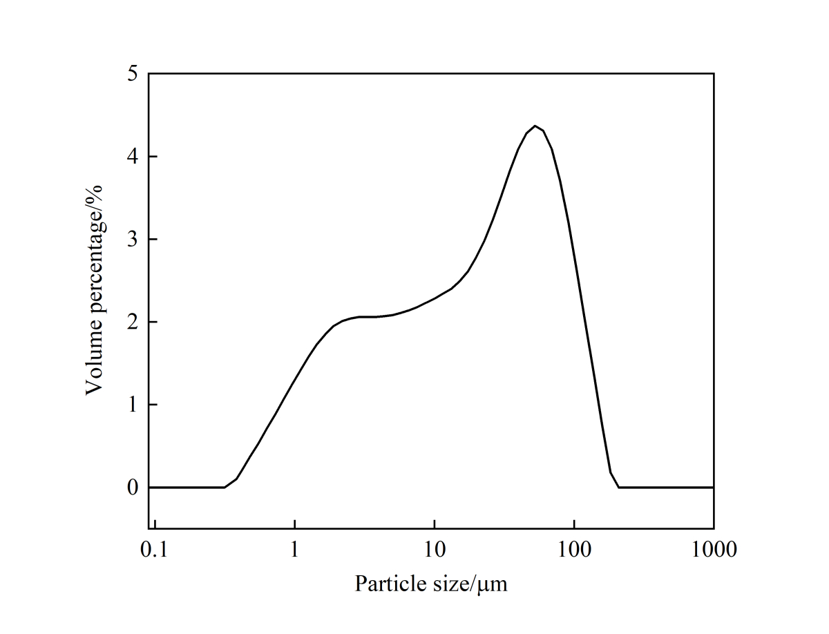
Grade S95 GBFS (GB/T 18046–2017 [29]) and Class F-Grade II FA (GB/T 1596-2017 [30]) were obtained from Hailuo Cement Corporation (Wuhu, China). As shown in Figure 2a, MDS was collected at a depth of approximately 1 m from the offshore area in Binhai Port of Yancheng City (Jiangsu Province, China). After drying in an oven at 105°C for 24 h, the MDS was ground in a ball mill for 10 min at a rotational speed of 70 r/min to disperse the agglomeration of particles and then produce the powder (Figure 2b). The moisture content of MDS was determined to be 42.7% based on the mass difference before and after drying. Following a period of natural sedimentation and drainage consolidation (typically 3–6 months) within confined disposal facilities, the MDS may reach a moisture content in the range of 30–50%. As shown in Figure 2c, numerous fine, flaky particles are observed in the SEM image of MDS powder, and significant variations are identified in the particle sizes. Particle size analysis was performed using a laser particle size analyzer, as shown in Figure 3. The median particle sizes (D50) of MDS, FA, and GBFS are 37.18 μm, 14.50 μm, and 11.48 μm, respectively. It should be noted that the MDS particles formed hard agglomerates after the oven-drying, which must be disaggregated and pulverized through ball milling process mentioned above. This process inevitably affected the particle size, specific surface area, and even the reactivity of the MDS. However, as this falls outside the scope of the present study, it will not be further investigated here.
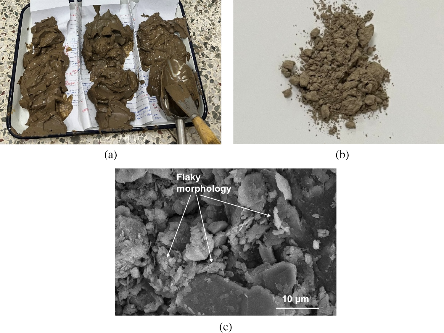
Figure 2 Photograph of (a) MDS slurry, and (b) photograph and (c) SEM image of MDS powder after drying and grinding
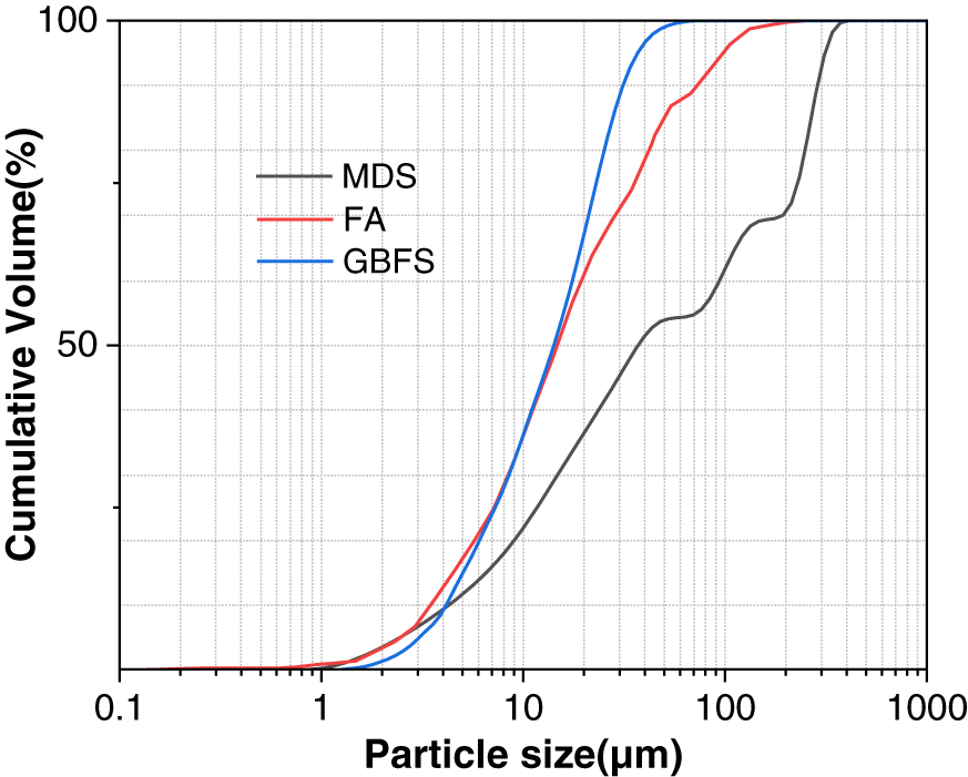
Figure 3 Cumulative particle size distribution curves of raw materials
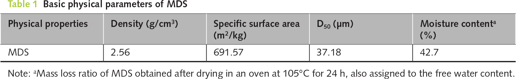
The basic parameters of MDS are presented in Table 1. Compared to previous studies, the MDS used in this work exhibits smaller particle size [3, 31]. During the natural sedimentation process of MDS, coarser particles tend to deposit in the surface layer due to gravitational settling, while finer particles gradually settle to deeper layers, resulting in a characteristic gradation of particle size with depth. The sampling depth of 1 m may be one of the primary reasons for the finer particle size. Additionally, the ball milling of the hard agglomeration of MDS after oven-drying not only dispersed the agglomeration of particles but also provided a certain grinding effect.
The chemical compositions of raw materials were determined by X-ray fluorescence (XRF) analysis, and the results are summarized in Table 2. The MDS is primarily composed of Si, Al, Ca, and Fe. The phase composition was analyzed using X-ray diffraction (XRD). As shown in Figure 4, the XRD pattern of MDS does not exhibit a distinct hump, indicating a low content of amorphous phase and consequently low pozzolanic reactivity. The crystalline phases identified mainly include calcite (CaCO3, PDF No. 85-849), quartz (SiO2, PDF No. 85-794), muscovite (KAl2Si3AlO10(OH)2, PDF No. 76-929), and clinochlore ((Mg,Fe)6(Si,Al)4O10(OH)8, PDF No. 29-701). In comparison, the XRD patterns of GBFS and FA show broad humps in the 20–40° and 15–35° ranges, respectively, corresponding to the presence of Ca-Si-Al rich and Si-Al rich amorphous glassy phases. Additionally, minor crystalline phases such as calcite, quartz, mullite (Al2(Al2.8Si1.2)O9.6, PDF No. 79-1276), and åkermanite (Ca2MgSi2O7, PDF No. 74–990) were also detected.
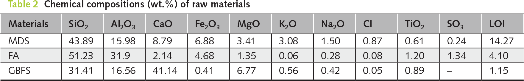
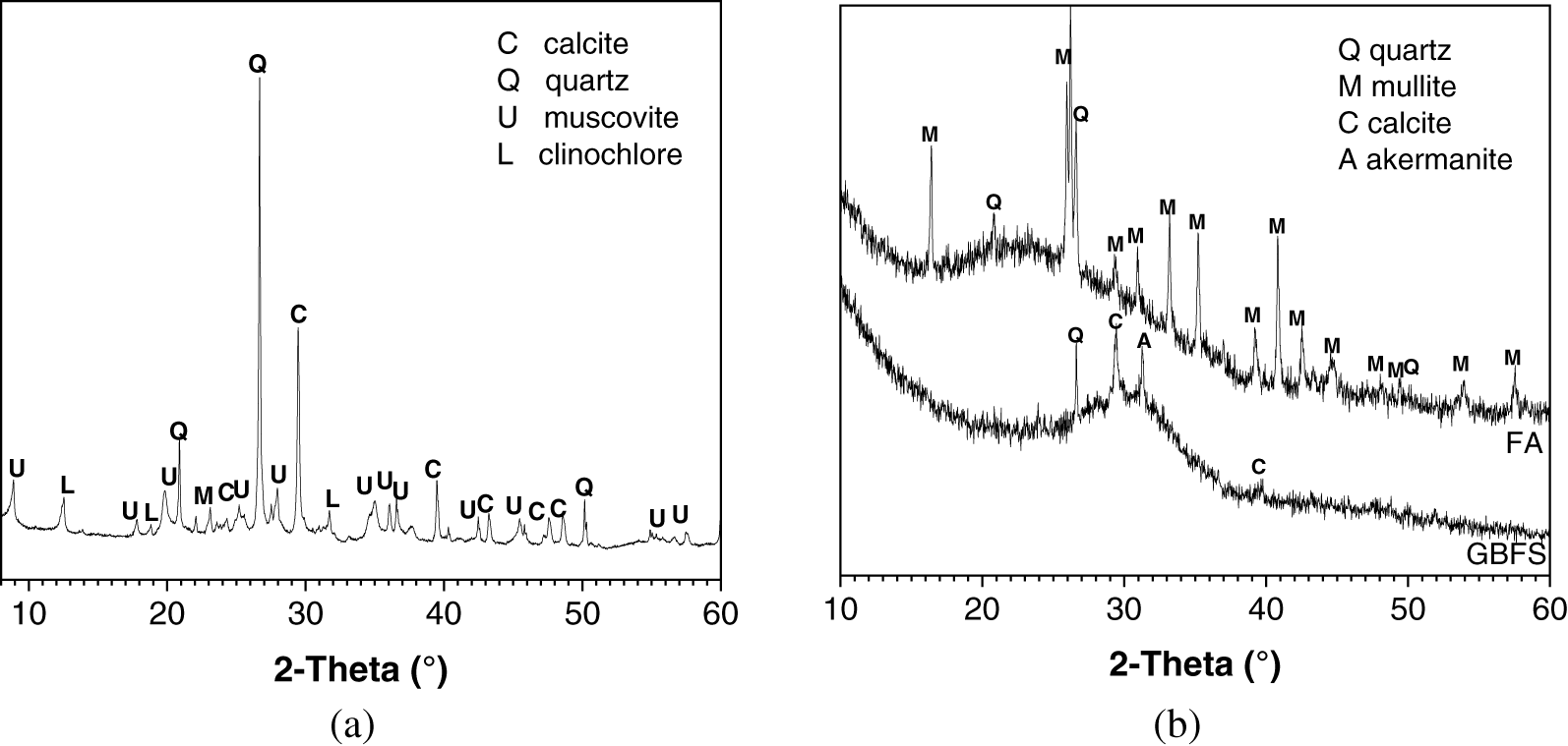
Figure 4 XRD patterns of raw materials: (a) MDS, (b) FA and GBFS
Figure 5 shows the thermogravimetry-derivative thermogravimetry (TG-DTG) curves of MDS. The mass loss peak near 70°C is attributed to the evaporation of free and physically bound water. Dang et al. [6] reported that the continuous mass loss occurring in the range of around 200–400°C was assigned to the elimination of organic matter present in MDS. The peak around 540°C corresponds to the dehydroxylation of clinochlore and muscovite, and the peak near 690°C is associated with the decarbonation of calcite. The mass loss observed in the range of 780–960°C is related to the re-crystallization of clinochlore [6].
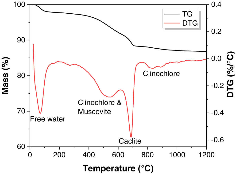
Figure 5 TG-DTG curves of MDS
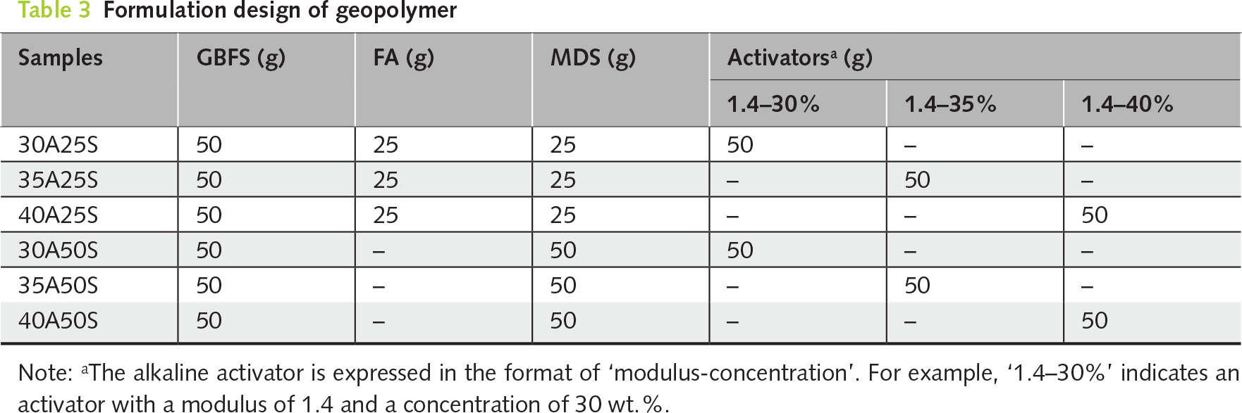
The alkaline activator of sodium silicate solution with 1.4 modulus (molar ratio of SiO2/Na2O) and 30/35/40 wt.% concentrations ((Na2O+SiO2)/(Na2O+SiO2+H2O)) was prepared by blending commercial water glass (SiO2 = 30.3 wt.%, Na2O = 12.8 wt.%) with NaOH pellets (≥96 wt.%) and tap water through adjusting the mixing ratios among the three components. The commercial water glass was provided by U-Rui Refractory Materials Co., Ltd. (Jiaxing, China).
In this experimental design, the total proportion of geopolymer precursors was normalized to 100%, comprising GBFS, FA, and MDS. Due to the undefined pozzolanic potential of MDS, this study proceeded under the hypothesis that MDS functioned as a reactive precursor. This assumption allowed for the formulation of the binder ratio before further mechanistic validation. A fixed 50% GBFS content was applied to all the formulations. The MDS content varied as 25% and 50% to evaluate its influence on compressive strength of geopolymer, whereas FA was used to supplement the remaining precursor. Meanwhile, the activator concentrations were set at 30%, 35%, and 40%, respectively. As shown in Table 3, six formulations were established with different MDS content and activator concentration. For example, the formulation 30A25S denotes an activator concentration of 30%, with the precursor materials comprising 25% MDS, 50% GBFS, and 25% FA by mass. A liquid activator to solid precursor ratio of 0.5 was set as constant to prepare fresh paste. The cubic specimens (30 mm × 30 mm × 30 mm) were cast and cured in the standard curing room (20 ± 1°C, relative humidity ≥ 90%) for the following tests.
The compressive strengths of 3-, 7-, and 28-cured specimens were assessed using a WHY-200 Auto Test Compression Machine. The loading rate was set as 2400 ± 200 N/s. Each data point represents the average of three measurements to ensure reliability.
Following the strength test, fragments from the crushed 28-day cured specimens were ground into fine powder for phase analysis by XRD on a SmartLab 9 kW Rigaku diffractometer. To further examine the thermal behavior and phase transformation, TGA was conducted using a STA 499 C NETZSCH instrument under a nitrogen atmosphere. The test was conducted for heating samples from 40 to 800°C at a rate of 10°C/min. The thermogravimetry (TG) and corresponding derivative thermogravimetry (DTG) curves were recorded.
Previous studies [16, 32] indicated that the GBFS-based geopolymers were characterized by compact pore structure, with pore size predominantly concentrated at around 10 nm. Consequently, nitrogen adsorption technique was selected as the most appropriate technique for characterizing such a pore size range. For pore structure evaluation, sieved particles (1–3 mm) obtained from the crushed 28-day cured specimens were analyzed by nitrogen adsorption using a Micromeritics TriStar II 3020 instrument, and the pore structure data were calculated using the Brunauer-Emmett-Teller (BET) method. Additionally, particles of about 5 mm in size were selected from the crushed 28-day cured specimens. These samples were embedded in resin and progressively polished. The resulting cross-sectional area was coated with a gold layer for examination by Backscattered Electron (BSE) imaging method using Nova Nano-SEM 450 FEI field emission scanning electron microscope with energy dispersive spectroscopy (SEM-EDS). For each mixture at a specified curing age, BET and BSE analyses were performed once to capture the representative microstructural features.
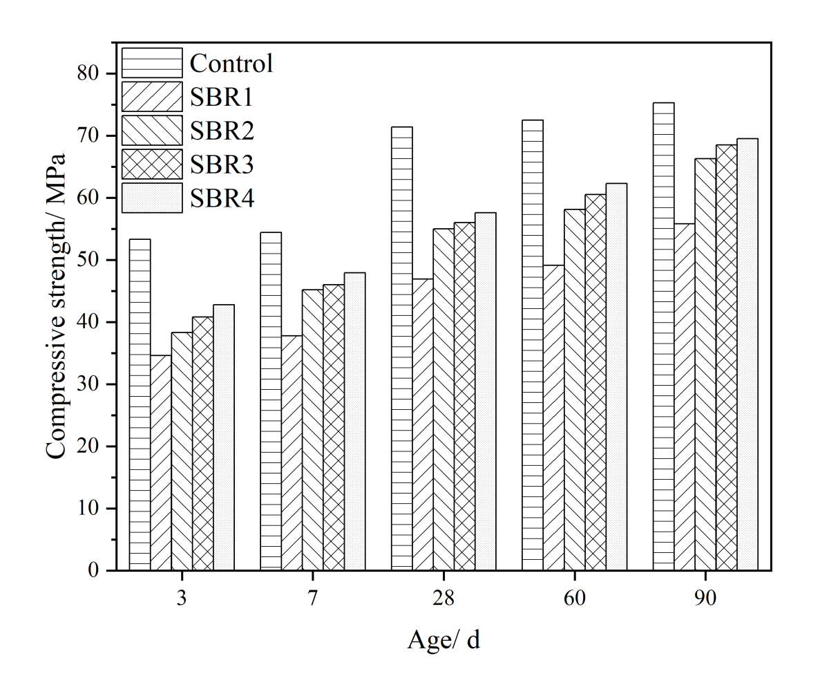
Figure 6 illustrates the effects of MDS content and activator concentration on the compressive strengths of geopolymers at 3, 7, and 28 days of curing age. The 3-day compressive strengths were above 30 MPa, indicating the rapid early-age strength development. When the MDS content was 25% (Figure 6a), the 3-day compressive strengths ranged from 36.8 MPa to 45.1 MPa, while the 28-day compressive strengths ranged from 58.4 MPa to 71.5 MPa. Increasing the MDS content to 50% (Figure 6b) reduced the 3-day and 28-day compressive strengths to the ranges of 31.2–36.3 MPa and 53.7–64.2 MPa, respectively. Considering that the increased MDS content correspondingly replaced FA in the formulation, it indicated that MDS exhibited lower pozzolanic reactivity compared to FA. This finding is consistent with previous research that calcination at a temperature range from 650 to 850°C was required to enhance the reactivity of MDS [6]. However, it was reported by Dang et al. [6] that even after calcination, MDS addition still caused a significant reduction in the strength development of OPC. To meet the strength requirements of P.O 42.5.5 OPC(GB/T 175-2023 [33]), the maximum content of MDS calcined at 650°C must be limited to less than 35%. In comparison, the strength values reported in this work for the geopolymer binders still meet or even exceed those of Grade 52.5 OPC, thereby confirming the feasibility of using 50% MDS for geopolymer preparation.
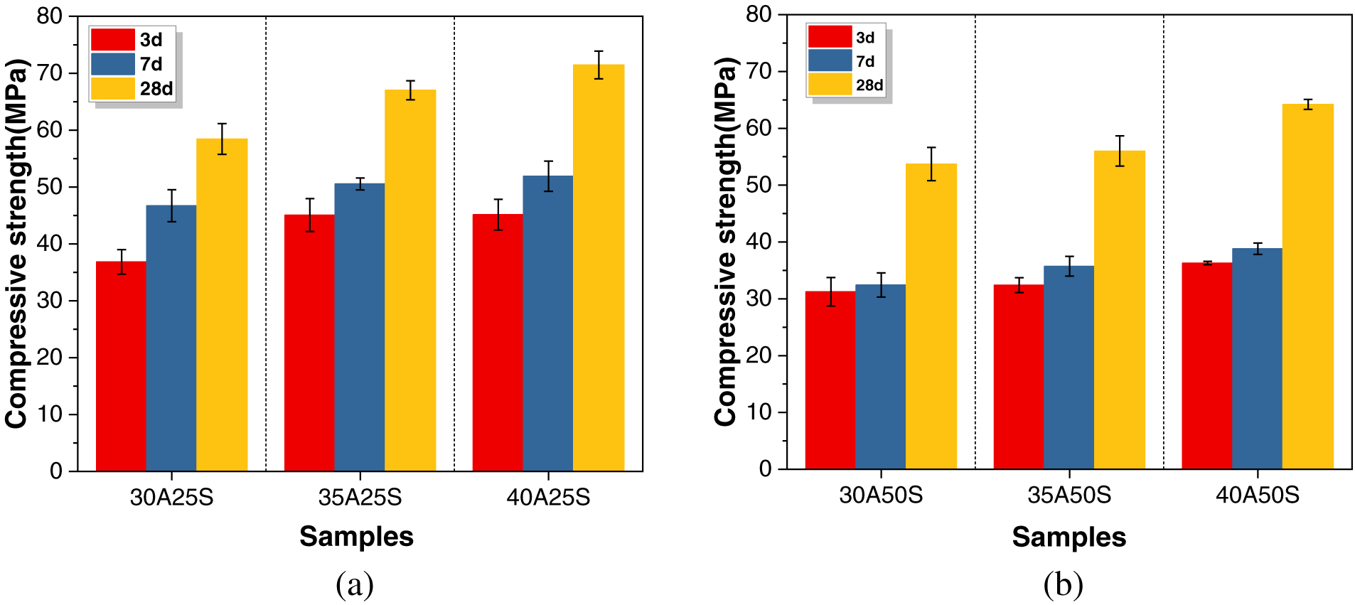
Figure 6 Compressive strengths of geopolymer binders synthesized with (a) 25% MDS and (b) 50% MDS
Increasing the activator concentration from 30% to 40% resulted in enhanced compressive strengths across all formulations, with a more pronounced improvement observed in the binders containing 25% MDS. The higher activator concentrations are more effective in activating precursors with higher reactivity, such as GBFS and FA.
Figure 7 presents the XRD patterns of geopolymer binders at 28 days of curing. C-(N)-A-S-H gel phase is the main strength-contributing hydration product formed in all binders as reflected by a diffuse intensity hump centered at approximately 29° 2θ (Ca5Si5Al(OH)O17·5H2O, PDF No. 29–331) [34]. The primary crystalline phases, including quartz, mullite, muscovite, calcite, and clinochlore, originate from the unreacted components present in GBFS, FA, and MDS. Specifically, the peak intensities of muscovite and clinochlore as the main crystalline phases identified in MDS increase in correlation with the MDS content. In addition, since the quartz peak intensity in MDS is higher than that in FA, increasing the MDS content as a replacement for FA leads to higher intensities of the quartz peaks in the resulting geopolymer binders. Increasing the activator concentration leads to the formation of a new crystalline product, gaylussite (Na2Ca(CO3)25H2O, PDF No. 21-0343), detected in both 40A25S and 40A50S. The elevated concentration of Na+ ions and alkalinity in the pore solution provided by the higher activator concentration results in a more intensive carbonation in the skeleton during the curing period [35]. Zhang et al. [36] also illustrated the phenomenon of subflorescence identified in the FA-based geopolymer prepared with the sodium silicate activator, which was regarded as an extended efflorescence occurring beneath the surface of specimen. Yao et al. [32] reported that the efflorescence crystal deposits were mainly composed of calcite and gaylussite.
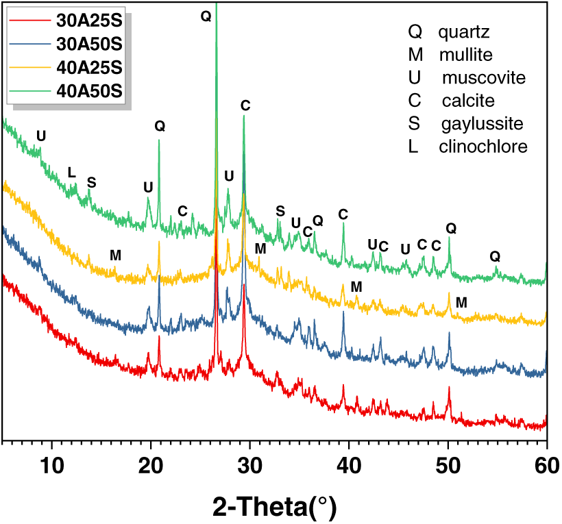
Figure 7 XRD patterns of 28-day cured geopolymer binders
Figure 8 presents the TG-DTG curves of the 28-day cured geopolymer binders, and Table 4 summarizes the corresponding mass loss data. The mass loss peak observed between 40–200°C primarily corresponds to the evaporation of free water and the removal of physically and chemically bound water from the C-(N)-A-S-H gel phase. Increasing the MDS content results in a slight increase in the intensity of this mass loss peak. This is not attributed to the improved degree of hydration, but rather to the higher physically and chemically bound water content inherent in the incorporated MDS, as well as the elimination of organic matter [6]. The TG analysis of MDS (shown in Figure 5) also indicates that the progressive mass loss occurs after heating to 105°C and persists up to 200°C, suggesting the physically and chemically bound water present in MDS cannot be completely removed by oven-drying at 105°C. In comparison, increasing the activator concentration enhances intensity of this mass loss peak, which is mainly attributed to the promoted hydration and reaction degree. The mass loss peak in the range of 600–800°C is associated with the decarbonation of calcite. It is worth noting that a higher MDS content intensifies this mass loss peak, likely due to the relatively high calcite content supplied by MDS.
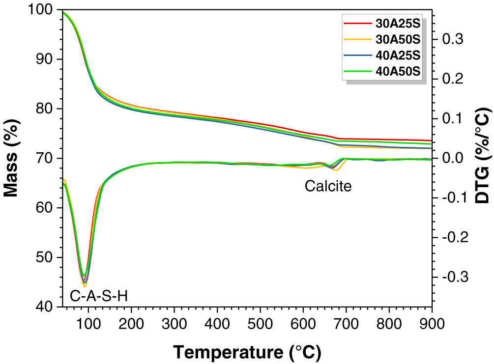
Figure 8 TG-DTG curves of geopolymer binders
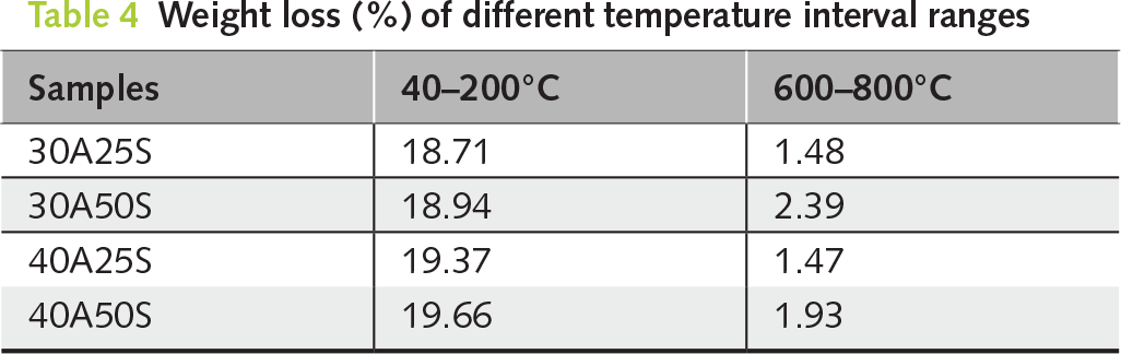
Figure 9 shows the pore structure analysis of geopolymers at 28 days of curing age, and the relative parameters are tabulated in Table 5. Figure 9a, 9b displays the pore size and pore volume distribution curves, indicating that the pores are predominantly distributed within the range of 1–100 nm. This is consistent with previous literature, which identified that the geopolymer based on GBFS exhibited a denser pore structure than OPC [37].

Figure 9 Pore structure analysis of geopolymer binders: (a) pore size distribution curves, (b) pore volume distribution curves and (c) cumulative pore volume histogram
The pores can be preliminarily classified into gel pores (<10 nm) and capillary pores (10–100 nm) [38]. The corresponding pore volume distribution is shown in Figure 9b. Increasing the MDS content significantly increases the average pore size from 13.20 nm (30A25S) and 17.04 nm (40A25S) to 16.12 nm (30A50S) and 21.30 nm (40A50S), respectively. This can be attributed to two main factors. On one hand, the incorporation of low-reactivity MDS has detrimental effects on the degree of hydration and the formation of C-(N)-A-S-H gel phase, thereby reducing the volume of gel pores. On the other hand, the incorporation of MDS with larger particle size affects the dense packing within the hardened skeleton, leading to increases in cumulative pore volume from 0.0664 cm³/g (30A25S) and 0.0294 cm³/g (40A25S) to 0.0900 cm³/g (30A50S) and 0.0395 cm³/g (40A50S), respectively. This pore structure coarsening effect should be one of the primary reasons for the compressive strength reduction identified in the geopolymer binders with higher content of MDS.
Amar et al. [7] employed mercury intrusion porosimetry (MIP) technique to investigate the effect of 850°C calcined MDS addition on the pore structure of OPC mortar. It was reported that the incorporation similarly resulted in an increase in the total porosity of mortar, which was primarily attributed to an increase in the interfacial area of MDS particles. Consequently, to mitigate the adverse effects of incorporating calcined MDS on the pore structure, compressive strength, and freeze-thaw resistance, it was advisable to limit its content to below 10% [7]. Zhao et al. [12] reported that when using dried MDS as a substitute for ordinary Portland cement (OPC), the compressive strength of mortar with 20% cement replaced by MDS was superior to that of mortar made with CEM II/A-LL 32.5 cement containing a similar proportion of limestone as the sediment substitution. Although increasing the MDS content led to a higher total porosity, a refinement of pore size distribution was also identified. This suggested that MDS acted as more effectively fillers than limestone to positively influence the cement hydration [12]. However, it should be noted that the recommended MDS contents in the above cases remain substantially lower than the levels utilized for geopolymer formulations in this work.
The cumulative pore volume of binders with 40% activator concentration is lower than that of binders with 30% activator concentration, indicating that increasing the activator concentration contributes to a denser pore structure. However, the average pore size of the 40% activator binders is larger than that of the 30% activator binders, mainly due to that most pores in the former cases belong to the capillary pores within the 10–100 nm pore size range. The enhanced degree of hydration under higher activator concentration consumes more pore solution and promotes the formation of more capillary pores. This plays a dominant contribution to enhancing the compressive strengths of the binder with higher activator concentration.
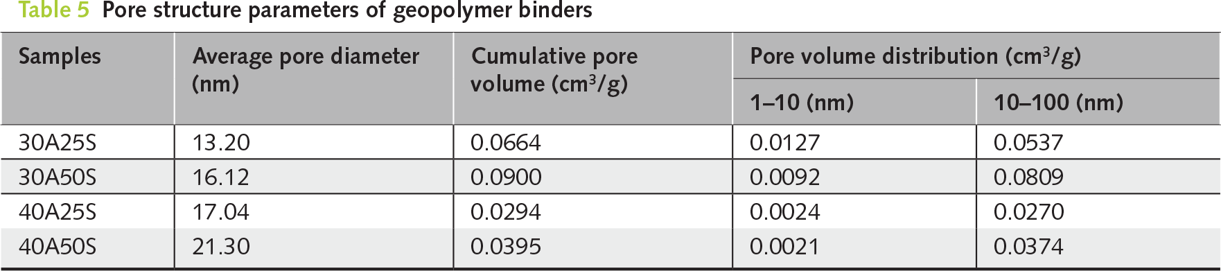
Figure 10 shows the BSE images of 40A25S and 40A50S at 28 days of curing age. Both Figure 10a, 10b exhibits the typical morphology of geopolymer cross-section area, with light gray spherical FA particles and irregularly shaped GBFS particles embedded in a dark gray matrix composed of C-(N)-A-S-H gel phase [39]. A layer of dark gray hydration products is observed on the edge of GBFS particles, indicating the relatively higher solubility and degree of hydration of GBFS than other precursors [40]. A certain amount of crack propagation is identified in the matrix, which is primarily attributed to the rapid development of shrinkage stress within the hardened skeleton.
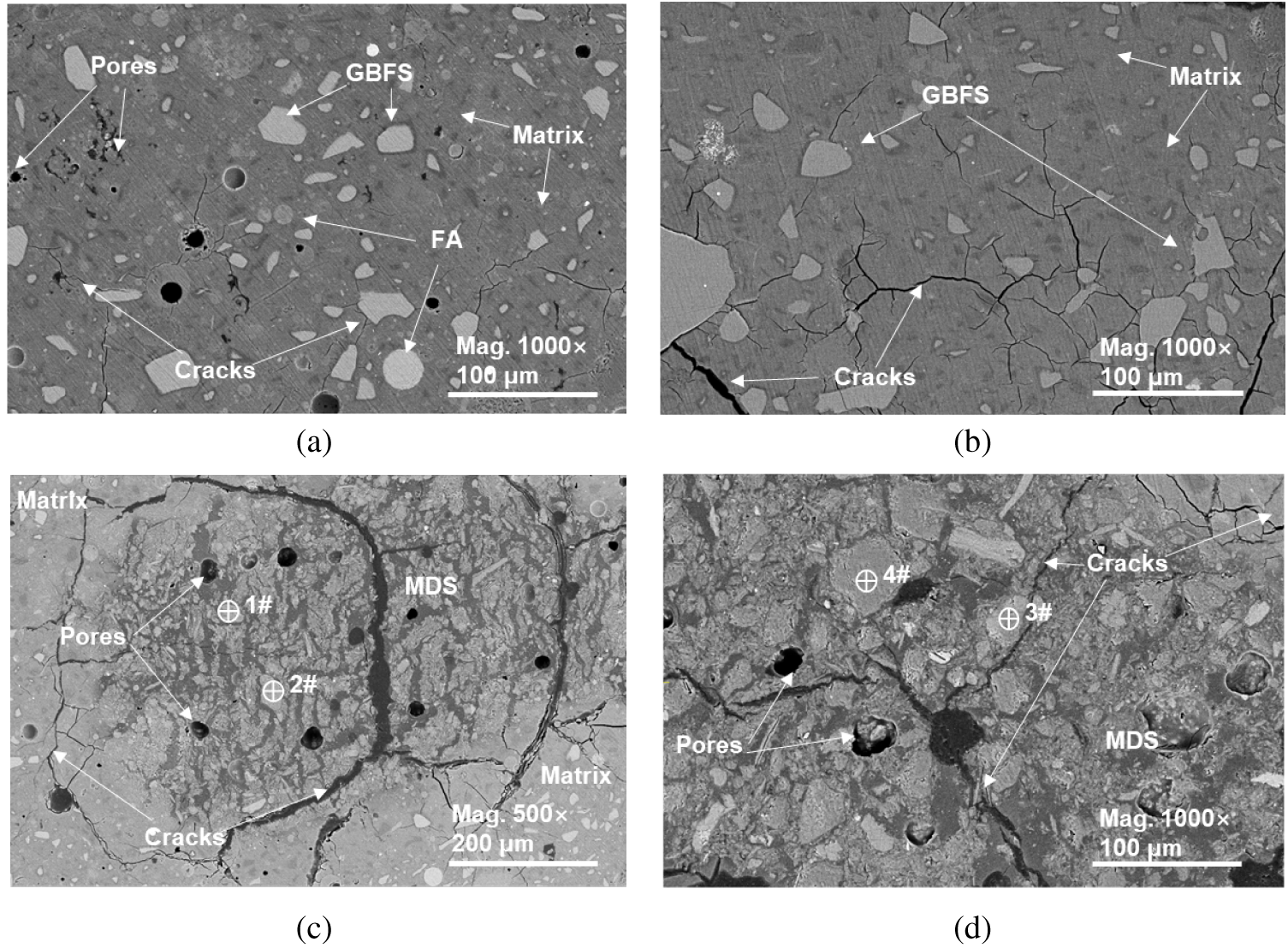
Figure 10 BSE images of geopolymer binders: (a,c) 40A25S and (b,d) 40A50S
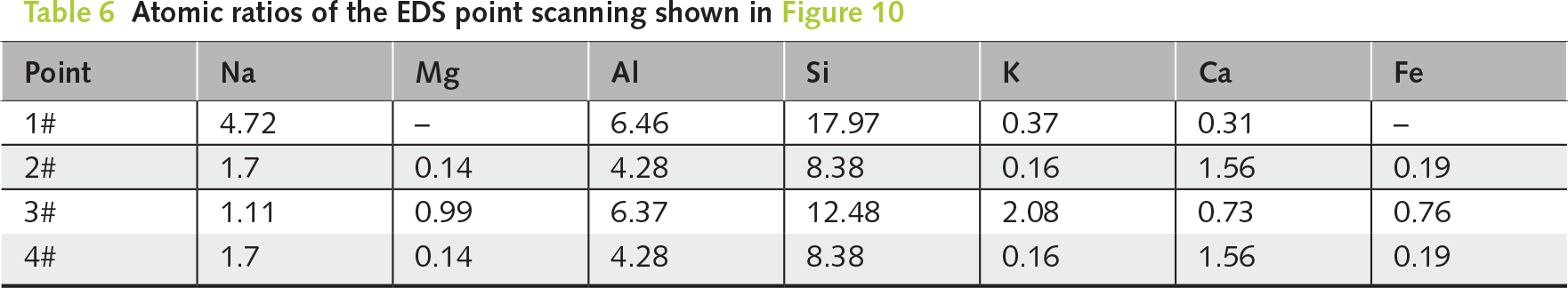
Figure 10c, 10d shows the morphology of MDS particles embedded in the matrix of 40A25S and 40A50S, respectively. The EDS point analysis tabulated in Table 6 confirms that the MDS particles are rich in Si and Al components. The MDS particles have large particle size and exhibit a loose lamellar stacking structure. This is consistent with the particle morphology of MDS shown in Figure 2c, mainly due to the presence of numerous flaky muscovite crystalline phases. During the mixing process, these particles enhance the water demand, consequently generating numerous pores during the hardening of the binder and amplifying the shrinkage stress induced by capillary water loss. This appears to affect the structural stability of the matrix. Therefore, penetrating cracks are formed and mainly distributed near the MDS particles, providing further explanation for the compressive strength loss associated with the incorporation of MDS.
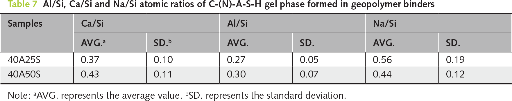
EDS point scanning statistical analysis is performed on the matrix to investigate the effect of MDS addition on the chemical compositions of C-(N)-A-S-H gel phase. Al/Si versus Ca/Si and Na/Si versus Ca/Si atomic ratios are shown in Figure 11, and the average values are tabulated in Table 7. The mean Ca/Si and Al/Si ratios for the 40A25S and 40A50S binders range from 0.37–0.43 and 0.27–0.30, respectively. These values fall well within the established ranges of 0.32 ≤ Ca/Si ≤ 1.11 and 0.21 ≤ Al/Si ≤ 0.40 reported in the majority of studies on alkali-activated GBFS using NaOH or Na2O⸳mSiO2⸳xH2O activators [41, 42]. This suggests that the addition of MDS does not exert a significant effect on the chemical compositions of the C-(N)-A-S-H gel phase. Increasing the MDS content leads to slight increases in both the Ca/Si and Al/Si atomic ratios of the gel phase, probably due to the dilution effect caused by the incorporation of less reactive precursor. Compared to 40A25S, the further substitution of 50% FA with MDS in 40A50S effectively increases the amount of alkali activator available for GBFS hydration per unit volume. The highly alkaline liquid environment promotes the dissolution of Ca and Al from GBFS, thereby increasing the Ca/Si and Al/Si ratios. Concurrently, the observed decrease in the Na/Si ratio indirectly suggests the dilution effect. The dissolution of Si from GBFS is also enhanced, although the dissolution seems to be less pronounced than those of Ca and Al from GBFS.
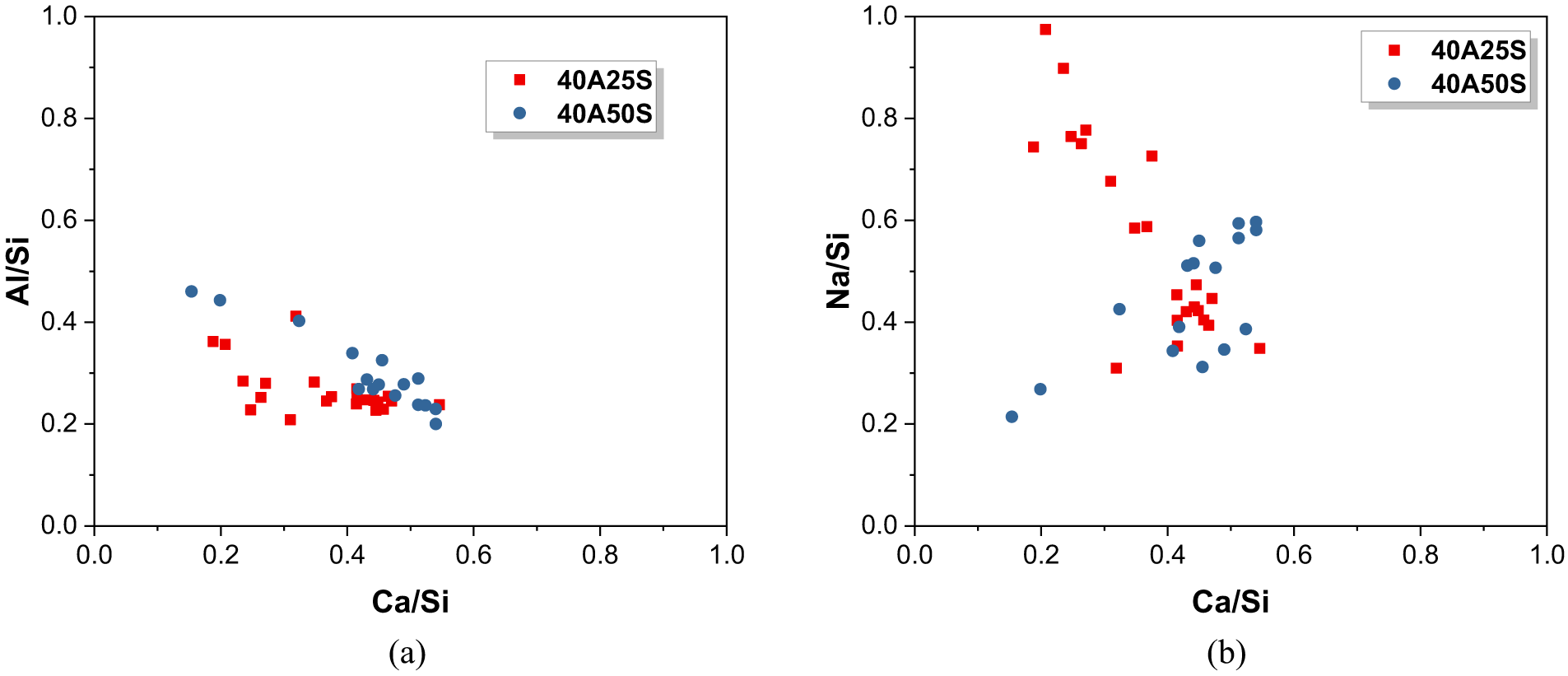
Figure 11 EDS point scanning analysis of the C-(N)-A-S-H gel phase formed in geopolymer binders: (a) Al/Si versus Ca/Si and (b) Na/Si versus Ca/Si atomic ratios
The MDS used in this study was sampled at a depth of approximately 1 m from the offshore area of Binhai Port in Yancheng, Jiangsu Province, China. Following oven-drying at 105°C in the laboratory, this study investigated the feasibility of utilizing MDS as a precursor in GBFS-FA geopolymer binders. The microstructural evolution and mechanical performance were systematically evaluated, leading to the following conclusions:
The MDS predominantly consists of crystalline phases of quartz, calcite, muscovite and clinochlore. Current processing with oven-drying and short-duration ball-milling is insufficient to activate the dormant pozzolanic potential of MDS, which remains basically as an inert filler in the binder. Binders containing 25% MDS achieve 28-day compressive strengths of 58.4–71.5 MPa. Although increasing MDS content to 50% results in a strength reduction to 53.7–64.2 MPa, these values remain comparable to or exceeding the requirements of Grade 52.5 ordinary Portland cement.
An increase in MDS content from 25% to 50% causes a dilution effect in geopolymer, raising the Ca/Si and Al/Si ratios of the C-(N)-A-S-H gel without generating new crystalline products. The strength decline is primarily attributed to the pore structure coarsening effect, as evidenced by increased cumulative pore volume and average pore diameter, which is driven by the low reactivity, loose morphology, and organic contaminants inherent in MDS.
A higher activator concentration promotes the degree of alkali-activation, contributing to a denser pore structure with lower cumulative pore volume, but also inducing the formation of gaylussite due to carbonation.
While this study demonstrates the potential of MDS in geopolymer synthesis, several critical challenges remain for large-scale engineering adoption. Future research should prioritize synergistic activation strategies, such as coupled thermal calcination and extended mechanical grinding, to break down crystalline clay minerals and enhance the reactivity of MDS in geopolymerization kinetics. It should be noted that these findings are currently in the laboratory stage. Transitioning to large-scale production will necessitate extensive engineering performance evaluations. Establishing a robustness framework to handle feedstock variability of MDS is essential. Beyond mechanical strength, the long-term durability of MDS-geopolymers requires rigorous quantification. The high concentration of chloride ions introduced by MDS poses a significant risk of steel reinforcement corrosion. Consequently, current applications should be restricted to unreinforced mass concrete or precast ecological units (e.g., tetrapods, artificial reefs). Additionally, the leaching behavior of heavy metals or organic pollutants from the MDS must be evaluated to ensure environmental safety in marine ecosystems.
Acknowledgement
The financial support from National Natural Science Foundation of China (51702278), and the Graduate Research and Innovation Projects of Jiangsu Province (KYCX24_XZ006, KYCX24_XZ048).
Funding Statement
This research was funded by National Natural Science Foundation of China (51702278), and the Graduate Research and Innovation Projects of Jiangsu Province (KYCX24_XZ006, KYCX24_XZ048).
Author Contributions
The authors confirm contribution to the paper as follows: Conceptualization, Tao Yang; methodology, Qin Lin and Wen Chen; validation, Qin Lin and Wen Chen; formal analysis, Qin Lin and Wen Chen; investigation, Qin Lin and Wen Chen; data curation, Wen Chen, Xuelong Qin, Letian Chen, Zhipeng Zhou and Zheng Wei; writing—original draft preparation, Qin Lin and Wen Chen; writing—review and editing, Tao Yang; visualization, Wen Chen and Xuelong Qin; supervision, Tao Yang; project administration, Qin Lin; funding acquisition, Tao Yang. All authors reviewed and approved the final version of the manuscript.
Availability of Data and Materials
The data that support the findings of this study are available from the Corresponding Author, [Tao Yang], upon reasonable request.
Ethics Approval
Not applicable.
Conflicts of Interest
The authors declare no conflicts of interest.
[1] Carreira C, Bollwerk SM, Lønborg C. A review on beneficial use of dredged marine sediment. Anth Coasts. 2025;8(1):12. doi:10.1007/s44218-025-00076-y.
[2] Solanki P, Jain B, Hu X, Sancheti G. A review of beneficial use and management of dredged material. Waste. 2023;1(3):815–40. doi:10.3390/waste1030048.
[3] Chu SH, Yao JJ. A strength model for concrete made with marine dredged sediment. J Clean Prod. 2020;274(4):122673. doi:10.1016/j.jclepro.2020.122673.
[4] Siham K, Fabrice B, Edine AN, Patrick D. Marine dredged sediments as new materials resource for road construction. Waste Manag. 2008;28(5):919–28. doi:10.1016/j.wasman.2007.03.027.
[5] Zentar R, Dubois V, Abriak NE. Mechanical behaviour and environmental impacts of a test road built with marine dredged sediments. Resour Conserv Recycl. 2008;52(6):947–54. doi:10.1016/j.resconrec.2008.02.002.
[6] Dang TA, Kamali-Bernard S, Prince WA. Design of new blended cement based on marine dredged sediment. Constr Build Mater. 2013;41:602–11. doi:10.1016/j.conbuildmat.2012.11.088.
[7] Amar M, Benzerzour M, El Mahdi Safhi A, Abriak NE. Durability of a cementitious matrix based on treated sediments. Case Stud Constr Mater. 2018;8:258–76. doi:10.1016/j.cscm.2018.01.007.
[8] Mecherivalappil CR, Kasthurba AK, Banerjee S. Advancing resource recycling: a state-of-the-art review on utilisation potential of dredged marine sediments for sustainable construction applications. Innov Infrastruct Solut. 2025;11(1):29. doi:10.1007/s41062-025-02398-9.
[9] Li J, Xu G. Circular economy towards zero waste and decarbonization. Circ Econ. 2022;1(1):100002. doi:10.1016/j.cec.2022.100002.
[10] Wang S, Liu B, Zhang Q, Wen Q, Lu X, Xiao K, et al. Application of geopolymers for treatment of industrial solid waste containing heavy metals: state-of-the-art review. J Clean Prod. 2023;390:136053. doi:10.1016/j.jclepro.2023.136053.
[11] Snellings R, Suraneni P, Skibsted J. Future and emerging supplementary cementitious materials. Cem Concr Res. 2023;171:107199. doi:10.1016/j.cemconres.2023.107199.
[12] Zhao Z, Benzerzour M, Abriak NE, Damidot D, Courard L, Wang D. Use of uncontaminated marine sediments in mortar and concrete by partial substitution of cement. Cem Concr Compos. 2018;93(4):155–62. doi:10.1016/j.cemconcomp.2018.07.010.
[13] Zhong H, Zhang M. Engineered geopolymer composites: a state-of-the-art review. Cem Concr Compos. 2023;135:104850. doi:10.1016/j.cemconcomp.2022.104850.
[14] Miron GD, Kulik DA, Yan Y, Tits J, Lothenbach B. Extensions of CASH+ thermodynamic solid solution model for the uptake of alkali metals and alkaline earth metals in C-S-H. Cem Concr Res. 2022;152:106667. doi:10.1016/j.cemconres.2021.106667.
[15] Mei J, Yin C, Zhao Y, Niu Y, Xie A, Li S. Effect of calcium carbide slag on the durability of alkali-activated ground granulated blast furnace slag-fly ash cementitious system. ZKG Int. 2024;77(8):42–50. doi:10.1201/9781003082460-4.
[16] Yang T, Zhu H, Zhang Z, Gao X, Zhang C, Wu Q. Effect of fly ash microsphere on the rheology and microstructure of alkali-activated fly ash/slag pastes. Cem Concr Res. 2018;109:198–207. doi:10.1016/j.cemconres.2018.04.008.
[17] Liu J, Doh JH, Ong DEL, Liu Z, Hadi MNS. Methods to evaluate and quantify the geopolymerization reactivity of waste-derived aluminosilicate precursor in alkali-activated material: a state-of-the-art review. Constr Build Mater. 2023;362(5):129784. doi:10.1016/j.conbuildmat.2022.129784.
[18] Rashad AM, Essa GMF. Effect of ceramic waste powder on alkali-activated slag pastes cured in hot weather after exposure to elevated temperature. Cem Concr Compos. 2020;111:103617. doi:10.1016/j.cemconcomp.2020.103617.
[19] Xu R, Liu W, Wang A, Zhang Z, Chen J. Strength development, phase evolution, microstructure change and environmental leaching behavior of alkali-activated copper slag. Constr Build Mater. 2025;473:141037. doi:10.1016/j.conbuildmat.2025.141037.
[20] Fernández-Jiménez A, Maltseva O, Palomo A, Marian NM, Sturini M, Riccardi MP, et al. Valorisation of inorganic fractions of waste generated by hydrothermal treatment of sewage sludge in alkaline cement. Sustainability. 2025;17(12):5413. doi:10.3390/su17125413.
[21] Slimanou H, Bouguermouh K, Bouzidi N. Synthesis of geopolymers based on dredged sediment in calcined and uncalcined states. Mater Lett. 2019;251:188–91. doi:10.1016/j.matlet.2019.05.070.
[22] Lirer S, Liguori B, Capasso I, Flora A, Caputo D. Mechanical and chemical properties of composite materials made of dredged sediments in a fly-ash based geopolymer. J Environ Manage. 2017;191(1):1–7. doi:10.1016/j.jenvman.2017.01.001.
[23] Zouch A, Mamindy-Pajany Y, Bouchikhi A, Abriak NE, Ksibi M. Valorization of marine sediments in geopolymer mortars: physico-mechanical, microstructural and environmental investigations at laboratory scale. J Mater Cycles Waste Manag. 2022;24(3):1109–23. doi:10.1007/s10163-022-01382-0.
[24] Gao X, Yang T, Li X, Zhu X, Zhu Z, Zhu H, et al. Effects of U-phase formation on early-age autogenous shrinkage of one-part alkali-activated slag. Cem Concr Res. 2025;196(9):107938. doi:10.1016/j.cemconres.2025.107938.
[25] Li Z, Chen Y, Provis JL, Cizer Ö, Ye G. Autogenous shrinkage of alkali-activated slag: a critical review. Cem Concr Res. 2023;172:107244. doi:10.1016/j.cemconres.2023.107244.
[26] Zhang W, Xue M, Lin H, Duan X, Jin Y, Su F. Effect of polyether shrinkage reducing admixture on the drying shrinkage properties of alkali-activated slag. Cem Concr Compos. 2023;136(3):104865. doi:10.1016/j.cemconcomp.2022.104865.
[27] Li Z, Lu T, Liang X, Dong H, Ye G. Mechanisms of autogenous shrinkage of alkali-activated slag and fly ash pastes. Cem Concr Res. 2020;135:106107. doi:10.1016/j.cemconres.2020.106107.
[28] Cao R, Li B, You N, Zhang Y, Zhang Z. Properties of alkali-activated ground granulated blast furnace slag blended with ferronickel slag. Constr Build Mater. 2018;192(1):123–32. doi:10.1016/j.conbuildmat.2018.10.112.
[29] GB/T 18046-2017. Ground granulated blast furnace slag used for cement, mortar and concrete. Beijing, China: SAC; 2017. (In Chinese).
[30] GB/T 1596-2017. Fly ash for cement and concrete. Beijing, China: SAC; 2017. (In Chinese).
[31] Limeira J, Agullo L, Etxeberria M. Dredged marine sand in concrete: an experimental section of a harbor pavement. Constr Build Mater. 2010;24(6):863–70. doi:10.1016/j.conbuildmat.2009.12.011.
[32] Yao X, Yang T, Zhang Z. Fly ash-based geopolymers: effect of slag addition on efflorescence. J Wuhan Univ Technol Mater Sci Ed. 2016;31(3):689–94. doi:10.1007/s11595-016-1430-8.
[33] GB 175-2023. Common portland cement. Beijing, China: SAC; 2023. (In Chinese).
[34] L’Hôpital E, Lothenbach B, Kulik DA, Scrivener K. Influence of calcium to silica ratio on aluminium uptake in calcium silicate hydrate. Cem Concr Res. 2016;85:111–21. doi:10.1016/j.cemconres.2016.01.014.
[35] Diaz Caselles L, Balsamo B, Trincal V, Benavent V, Bertin M, Lahalle H, et al. Carbonation of alkali-activated materials: changes in mineralogical composition and pH, and qualitative estimation of corrosion risk. Mater Struct. 2025;58(4):112. doi:10.1617/s11527-025-02640-x.
[36] Zhang Z, Provis JL, Ma X, Reid A, Wang H. Efflorescence and subflorescence induced microstructural and mechanical evolution in fly ash-based geopolymers. Cem Concr Compos. 2018;92:165–77. doi:10.1016/j.cemconcomp.2018.06.010.
[37] Babaee M, Castel A. Water vapor sorption isotherms, pore structure, and moisture transport characteristics of alkali-activated and Portland cement-based binders. Cem Concr Res. 2018;113:99–120. doi:10.1016/j.cemconres.2018.07.006.
[38] Wang J, Wang X, Ding S, Ashour A, Yu F, Lv X, et al. Micro-nano scale pore structure and fractal dimension of ultra-high performance cementitious composites modified with nanofillers. Cem Concr Compos. 2023;141(4):105129. doi:10.1016/j.cemconcomp.2023.105129.
[39] Fang G, Wang Q, Zhang M. In-situ X-ray tomographic imaging of microstructure evolution of fly ash and slag particles in alkali-activated fly ash-slag paste. Compos Part B Eng. 2021;224:109221. doi:10.1016/j.compositesb.2021.109221.
[40] Fang G, Wang Q, Zhang M. Micromechanical analysis of interfacial transition zone in alkali-activated fly ash-slag concrete. Cem Concr Compos. 2021;119:103990. doi:10.1016/j.cemconcomp.2021.103990.
[41] Ben Haha M, Le Saout G, Winnefeld F, Lothenbach B. Influence of activator type on hydration kinetics, hydrate assemblage and microstructural development of alkali activated blast-furnace slags. Cem Concr Res. 2011;41(3):301–10. doi:10.1016/j.cemconres.2010.11.016.
[42] Richardson IG, Li S. Composition and structure of an 18-year-old 5M KOH-activated ground granulated blast-furnace slag paste. Constr Build Mater. 2018;168:404–11. doi:10.1016/j.conbuildmat.2018.02.034.